Dummy loads and smart choices
Understanding the design, operation and maintenance of RF terminations
April 1, 2005
Radio frequency engineers often wonder what RF termination is appropriate for a particular application. Their curiosity is well-justified, as there are several design differences, as well as maintenance and environmental considerations, which are important when choosing a termination.
The purpose of a termination (also known as a dummy load) is to absorb RF energy and turn it into heat. Many times the load takes the place of an antenna during transmitter testing. Other applications where terminations can be found are:
reject loads
hybrid combiners
isolators /circulators
transmitter tuning
system testing and calibration
An ideal load will provide a precisely matched absorption of unlimited RF energy over an unlimited frequency range while maintaining a perfect match (a voltage standing wave ratio, or VSWR, of 1:1).
In the real world, however, the matching quality of the load varies with frequency. Typically, the VSWR of a termination rises with increasing frequency, with the usable frequency range dependent on the point at which the VSWR becomes intolerable. Power-handling capabilities depend on physical size, construction, duty cycle of the applied signal and more. Selection of the optimum load for a given application involves a thorough understanding of load characteristics and design factors.
Following the laws of physics, a termination, or load, converts RF energy into heat. In most terminations, a resistive element is the device used to convert the RF energy into heat. For some applications, water is the means of conversion. Ideally, the heat should be disposed of in the quickest manner possible. To dissipate heat, a resistor is immersed in one of several dielectric mediums: air, water, oil or a water/ethylene glycol mixture. The heat transfer characteristics of the dielectric material determine the properties of the load and its suitability for various applications.
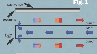
Water-cooled loads use pressurized water of proper temperature and flow rate to carry heat away from the resistive element. The water-cooling system can be sub-divided into two groups: water that is contained totally inside the resistor (Figure 1) and water that flows on both the inside and outside of the resistor (Figure 2). The high-strength compound of the resistor tube is a good thermally conductive material so that the heat generated by the RF energy is readily conducted through its comparatively thin wall. This substrate compound also isolates the water electrically from the fields inherent to the coaxial line.
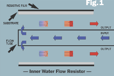
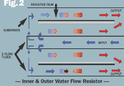
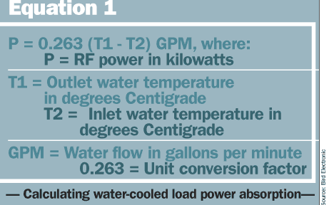
Water passing over the inner or inner/outer resistor surface carries away the generated heat. Unlike other terminations, there is practically no heat transfer to the outer housing of the load, even under full power application. Therefore, a very accurate measurement of power absorbed by the load can be easily calculated using Equation 1.
Water-cooled loads are, by far, the most efficient in transferring heat. Consequently, they also are the smallest in size, have high power-handling capabilities (up to 80 kW) and can operate in any installation orientation.
Oil-dielectric loads surround the resistive element with oil, which transfers heat to an exterior, finned shell for dissipation into the surrounding air. Oil-dielectric loads consist of a carbon film resistor on a ceramic substrate. The resistor is enclosed in an exponentially tapered housing. This provides a linear reduction in surge impedance directly proportional to the distance along the resistor.
When surrounded by the dielectric coolant, the characteristic impedance is 50 ohms at the front (connector end), 25 ohms at the mid-point and zero ohms at the rear where the resistor joins the housing, forming the return conductor of the coaxial circuit. This produces a uniform, practically reflectionless line termination.
These loads may be divided into two sub-groups: devices using only exterior cooling fins to radiate heat and devices using cooling fins combined with electric blowers. With the installation of electric blowers, air is forced past the cooling fins for an increase in power-handling capability.
Air-cooled loads use the properties of moving air to transfer the heat away from the resistive element. Typically, these loads are equipped with fans to move the air past the resistors. This type of load uses multiple tubular ceramic resistors combined in parallel.
This type of load design also will produce a very uniform and nearly reflectionless line termination. Electrically, this type of design, unlike other loads, appears as a high-pass device. At DC, the load will be a short circuit and therefore cannot be checked with an ohmmeter. Also, because air-cooled loads do not use oil or water as the dielectric medium, they tend to be larger in size; however, they require little maintenance and are quite reliable.
But when operating a load cooled by flowing air, the ability of the air to capture and transfer the heat away from the load is diminished. For this reason, the operating power level must be de-rated. Generally, oil-dielectric loads begin to de-rate at 5000 feet above sea level while air-cooled loads de-rate starting at 10,000 feet.
When considering a load for your application, operating conditions and maintenance should be explored. Systems operating at high altitudes, extreme temperatures or with poor water quality can have a significant effect on the decision-making process.
For example, while many factors will affect a water-cooled load’s ability to dissipate energy, one of the most critical is the quality of the water used. Water must be of sufficient quality and quantity to allow heat transfer from the resistive element to the outside. Any internal heat buildup could result in a catastrophic failure or a decrease in the life span of the load.
Water quality is measured in the U.S. as the amount of solids dissolved in the water and is expressed in parts per million, or ppm (e.g., 1 ppm equals 1 mg per liter). Standards for drinking, or potable, water are established by the U.S. Public Health Service at a maximum of 500 ppm of total dissolved solids. The total ppm count could consist of different materials, making it impossible to place a specific water conductivity figure on the limit.
The hardness of water refers to the content of calcium and magnesium salts, which may be bicarbonates, carbonates, sulfates, chlorides or nitrates. These salts in hard water form deposits or scale on the resistor as water is heated or evaporated. Think of scale as the particles that remain when a pan of boiling water completely evaporates.
Impurities and chemical additives in the water affect the electrical and thermal characteristics of the load. Salts in the water will result in a rapid increase in VSWR because of the accumulation of scale on the inside and/or outside surface of the ceramic tube resistor, depending on the water-flow design. Impurities and scale also increase the thermal resistance of the load, which can cause the load to overheat and fail. Because of the impurities and solids, salt water or any type of silt-laden water should not be used for cooling the load.
Just as important, de-ionized water should not be used as the load coolant. De-ionization allows the removal of particles as small as ions from a solution and is used to purify water and remove salts and other impurities. However, because this water is ion-starved, it will chemically attack the brass, copper and aluminum found in the water system and re-deposit some of the metals on the resistor. As a result, the load will overheat and fail rapidly.
Distilled water is water that has been heated to boiling to separate impurities from the water. The steam is then cooled and condensed back into pure liquid form. The impurities remain as residue in the steam kettle. This distillation system removes organic and inorganic chemicals, heavy metals, volatile gasses and other contaminants. Distilled water used as the coolant will yield the maximum life expectancy of the load and is the best solution if water quality is in question. Softened or de-mineralized water also is acceptable because of the lower amount of dissolved solids present.
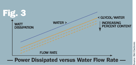
Where cooling systems are required to operate in below-freezing temperatures, additives are needed to lower the freezing point. Using a mixture of water and ethylene glycol (i.e., antifreeze or Dow Chemical Co.’s Dowtherm SR-1) protects against freezing and has outstanding corrosion-inhibiting advantages. However, a 40% SR-1 to 60% water mixture is only half as efficient as water in taking heat away from the resistor. A 50/50 mix is less than half (43.9%) as efficient. Since these mixtures are less efficient coolants, de-rating of the power level of the load or an increase in the water flow rate is required (Figure 3).
Oil-dielectric loads use silicone or refined mineral oil as the heat transfer medium, removing heat produced in the resistive element and transferring it to the finned outer shell and then into the surrounding air. Like the water-cooled loads, the life expectancy of an oil-dielectric load is directly related to the amount of internal heat produced. The maximum temperature rating for the oil and resistive film limits the power handling capability of the load.
The oil must stay below its maximum temperature to ensure that it doesn’t break down and form other compounds. Oil becomes more reactive to foreign substances at higher temperatures and can form compounds that do not have the same thermal or electrical properties of the original oil, resulting in an increase in VSWR and, potentially, failure.
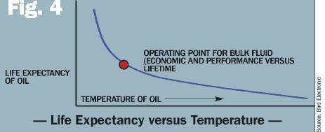
If an oil-dielectric load is operated under worst-case conditions — 50 Hz, at maximum rated power and maximum ambient temperatures — the rate at which the oil breaks down is much greater, and the oil should be changed every 100 to 250 hours of operation. If the same load were operated under less stressful conditions — 60 Hz, 80% of load-rated power and 25Þ C ambient temperature — the oil will need to be changed between 500 to 700 hours. Under the same conditions but at 60% of rated power, the life expectancy of the oil is greater than 4000 hours (Figure 4). The condition of the oil can be determined by color and odor. Oil that is dark or has a burned or pungent odor should be replaced.
Maintaining adequate spacing between oil-dielectric loads is important because the cooling fins are radiating heat. Positioning the loads too close together or to a wall will raise the ambient temperature and, as a result, increase the temperature of the oil. Generally, space oil-dielectric loads as follows to maintain adequate convection between the loads:
1 kW load: d = 12″ or 6″ from wall
2.5 kW load: d = 24″ or 12″ from wall
10 kW load: d = 30″ or 15″ from wall
Likewise, placing a cover or shroud over the oil-dielectric loads or mounting the load too close to the ceiling will prevent proper airflow.
Similarly, because air is the heat-conducting medium of an air-cooled load, care must be taken to avoid impeding the airflow or exceeding the maximum ambient air temperature. There is no need to filter the air as long as the air is reasonably clean. Similar to the oil-dielectric loads, spacing between other loads should be kept at a minimum of 12 inches, or 6 inches to the nearest wall.
Table 1: — Determining the proper RF termination — |
|---|
▪ What is the operating frequency? |
▪ What level of power and type of modulation is being applied? |
▪ What is the peak to average ratio of the signal being dissipated? |
▪ Are there harmonics present on the signal that may add to the total power being seen by the load? |
▪ Are there leakage paths from other components of the circuit that may be contributing to the total power level? |
▪ What will be the typical ambient temperature of the surrounding air? |
▪ Will there be adequate space between loads? |
▪ What is the quality of water? |
Table 2— Operation and maintenance characteristics of conventional loads —
Water | Air | Oil | |
|---|---|---|---|
Size | small | large | medium |
Weight | light | moderate | heavy |
Initial cost | low | higher | medium |
Power | high | moderate to high | low |
Maintenance | complex | simple | moderate |
Peak power | moderate | highest | high |
Overload tolerance | lowest | highest | moderate |
Altitude | 5000 feet | 10,000 feet | 5000 feet |
External temperature | coolest | cool | hot |
Katie Wright is an applications engineer for Bird Electronic. She has more than nine years of experience in RF receiver design and test and measurement equipment. She has been involved in developing precision power measurement equipment for RF transmission systems and semiconductor applications.


