Big signals at small cost
Bob Buckley, sheriff of Union Parish, La., knew he had a serious communications problem on his hands. The UHF two-way radio system that the parish operated did not allow him or his command staff to always know where his deputies were because of poor coverage. Union Parish borders Arkansas and is in an area of Louisiana that has many hills, bayous, lakes, rivers, and trees, resulting in numerous coverage holes. One could yell farther than the distance the radio transmissions would cover at some sites.
Before visiting Union Parish to determine what was wrong with the system, we first downloaded a copy of the FCC authorization in order to know the location of each of the sheriff’s stations. After reviewing this information and meeting with Buckley, we determined that a local dealer had put in two additional stations but had failed to update the license with the FCC. The radios were on the same authorized frequencies, but at the two additional tower sites. Correcting this licensing problem became our first priority.
We next visited the maverick sites and, using the proper testing equipment, discovered the following problems:
-
The Channel 2 West Tower radio had tripped a breaker and had become inoperative.
-
The Channel 2 Central Tower experienced a 36 dB reduction in duplexer sensitivity when the transmitter was activated. (The signal needed to be 4000 times stronger than was otherwise required.)
-
The Channel 1 East Tower had a bad jumper in the antenna transmission line.
-
The Channel 2 dispatch radio did not have control over the tower with which it was communicating.
-
None of the sites had lightning protection in any of the antenna transmission lines.
The sheriff suspended use of the maverick towers until the FCC authorization was corrected, which was accomplished quickly. A local radio dealer also was contacted, and most of the technical problems were corrected in short order. The next step was to address Union Parish’s coverage problems.
Buckley felt we could add a new site in the southeastern corner of the parish that would fix part of his coverage problems. However, this system modification did not solve the problem. In fact, we discovered that many of the radios in the field did not have all of the DCS/DPL codes programmed into them to bring up all of the towers. This is one of the primary reasons why Buckley never had good communications with the units in the field.
We also discovered some antenna problems — using our frequency domain reflectometry (FDR) sets — that were not apparent using just a wattmeter to test the antennas. FDR technology should be used for every installation and maintenance cycle to confirm that the antenna systems are working as designed.
Multiple vendors had previously contacted Buckley about installing a small trunking system in his parish, and all had promised this would solve his communications problems. What they did not tell him was that the parish’s infrastructure must be completely replaced, as well as all of the mobiles and portables. In addition, a microwave backhaul system that would link all of the sites together would have to be installed. The installation costs greatly exceeded his budget.
Our challenge, then, was to design a system that was easy to use, was 100% compatible with the existing mobile and portable equipment and was within the department’s budgetary constraints. As we were planning for the new system, we also were asked to improve communications for the other divisions within the sheriff’s department and to achieve better interoperability with all agencies in the parish and region. Our solution was to design a simulcast radio system with a multiple site receiver voting system.
The new system has two frequencies for patrol use (with multiple sites for each frequency), a receiver voter system and transmitters that are in a quasi-simulcast mode. We used UHF narrowband links to get the remote tower receiver signals back to the central radio tower and chose ICOM radios, partly because the price and performance specifications matched our requirements, but also because ICOM radios are available via state contracts. The company worked with us to modify the base radio repeaters to meet our specific needs.
A staging of the system before deployment demonstrated that the frequency stability was close enough to meet the narrowband rules for the UHF channels that were being used, but it was nowhere close to being good enough to qualify as simulcast. It was during the staging that we noticed an expected warble in the overlap areas, but it always varied in terms of frequency and amplitude. In addition, we noticed that the DCS squelch never failed to open. Further testing found that the 1 kHz lineup tone sounded clear, and that the warble was well below the amplitude of the tone. Consequently, the distortion was well within limits for the audio tone in the overlap region. The sheriff sent a representative from his office to the staging, and he concurred that the warble was well below the objectionable level.
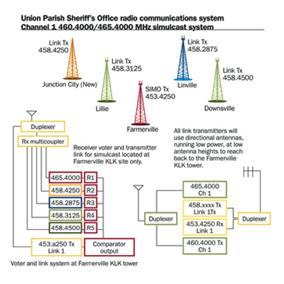
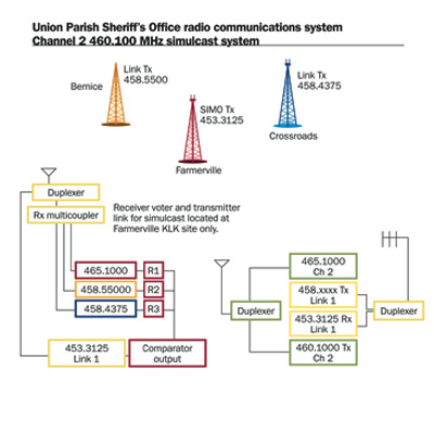
There was one fairly significant challenge in the early stages of the optimization: The mobile and portable radios could communicate with each other, but dispatch could not. After spending hours trying to determine what was different about the radio at the dispatch site, we discovered that one of the remote sites had a programming error in the link transmitter. This allowed the site to vote, but there was no audio. A disabling of that site on the receiver voter panel mitigated this until we could correct the programming problem.
As each site was brought up, the increase in coverage was immediately noticeable. Buckley was one of the first people to discover the extent of expanded coverage. He was in downtown Monroe — about 30 miles away in an adjacent parish — in an office building and was able to call dispatch from a walkie-talkie, something that would have been only a dream before the installation. A couple of days later, a deputy was able to call dispatch from Litroe, La., a small community about 20 miles from the parish’s dispatch center, using a walkie-talkie. Previously, this was an area of no signal coverage, even from mobile units.
We used DHE RV4-2 voters for this project. This voter works extremely well for this kind of system if it is aligned properly. A test count conducted using a portable unit had eight “votes” selecting all five receivers on Channel 1, and you could not hear the receiver change levels or audio in any way between the different sites. This is how a voter should work.
In watching the system operation, it became apparent that almost half of the radio units in the field have some kind of transmitter or antenna problems, as some of the radios work properly no matter where they are, while others never sound good or fail to vote to sites of which they should be in range. However, it is not unusual to see such results when making a major change in a new radio system using existing mobiles. The process of checking and repairing these problem radios is just beginning.
A RADIO PRIMER
Receiver voting
Receiver voting has been around since the 1960s. It is accomplished by having multiple receivers scattered throughout a geographic area, and all of the receiver audio signals are brought into a single site, compared to each other, and the best one is selected as the receiver that is repeated. The basic premise that makes this technology work is the strongest signal will have the lowest noise floor. The voter system compares all of the input signals, and only allows the one with the least noise to be passed back to dispatch and the other units.
For a voter to be working properly, all of the receivers must sound the same. This includes the audio level, and the overall sound. You do not want anyone to be able to say “that is the north receiver” because it sounds different from the rest. The initial system lineup requires that all of the receivers be perfectly matched to each other in every parameter. You will need high quality testing equipment to accomplish this.
With the newer digital formats, the received signal strength indication (RSSI) is part of the information that is conveyed in the link data, and the receiver with the strongest RSSI is the selected signal.
Coded squelch
Coded squelch is a signaling method where a radio receiver stays muted until the proper code is received along with the radio signal on a given radio channel. This code is usually at an audio level that is approximately 10-15% of the total authorized modulation of the channel. The usage of this coded squelch allows multiple users to share the same channel, and also keeps unwanted interference from bothering the users of a given radio channel.
Coded squelch comes in two varieties. The original method is to use a low frequency tone that is transmitted by the originating transmitter at a low modulation level. There are 38 separate tones in use today for this purpose. This system is known as Continuous Tone Coded Squelch System, or CTCSS. This is sold under trademark as Private Line (PL) by Motorola, or Channel Guard (CG) by GE-ERICSSON-M/A-COM. As some of the systems became more crowded, Motorola came up with a digital system that has 83 unique digital codes. They called this system Digital Private Line (DPL). The rest of the land mobile industry calls this Digital Coded Squelch System (DCS).
How the old system worked
The original system worked by using three repeaters for each channel. The channels were labeled as Channel 1 Main, Channel 1 East, Channel 1 West, Channel 1 Talk-Around, Channel 2 Main, Channel 2 East, Channel 2 West, and Channel 2 Talk-Around. As a unit traveled around the parish, the deputy would have to know where he was, then manually switch the radio to the channel that served that area. Each of the repeaters used a different DPL/DCS code to bring up that repeater’s receiver input, but they all had the same DPL/DCS code on the output, so that all of the traffic on the radio channel could be heard.
There were two problems with this system. First, not every deputy knew the area well enough to switch to the correct channel in a given area. The second problem was that the radio shop had set up different radios on different channels to accomplish the multiple-site system. In addition to dispatch not being able to tell a deputy to go to a given channel on his radio, some of the radios did not have the proper programming to all of the codes, and no matter which channel was chosen, a deputy in the field could not access the nearest repeater. Finally, even when all of the correct codes were in the correct channel locations, the last thing a deputy in pursuit of a suspect at 100-plus MPH wants to do is look at his radio and switch channels to keep up with the area of coverage for a given site.
UHF radio propagation
At UHF frequencies, radio signals are normally sent from the transmitter to the receiver in a mode called line of sight (LOS). This means that the antenna of the receiver needs to “see” the antenna of the transmitter for the signal to be heard. Moreover, the signal gets weaker as one gets further away from the transmitter. However, while obstructions such as buildings, trees, hills, and even people can block the true visual LOS, one can still get a signal from the transmitter to the receiver. Whether a path still exists is determined by how much signal is remaining after the attenuation of the free space loss and the obstructions. If the signal has a 40 dB margin above the receiver threshold at a given spot, and the building loss is 50 dB, then the receiver does not hear the transmitter in the building. At that same spot, if the building attenuation is only 39 dB, then you do hear the transmitter. This is how one can accurately predict the range of the radio system.
A second factor affecting radio propagation is a component of the signal strength called Rayleigh fading. This occurs when the signal reflects off surfaces and hits the receive antenna with the phase distorted such that the signal adds in some spots and subtracts from the original signal strength in others, often just inches apart from each other. The net result is that you can move your radio receiver antenna just a few inches and go from full signal strength with no noise to having no signal at all. All radio systems have this problem. If you are traveling in a vehicle, this sounds like popping in the receiver audio. If you are somewhat stationary, such as when using a walkie-talkie, you can go from full readability to none. This is why the dispatcher occasionally will tell radio users to move just a little bit in any direction.
The use of multiple antennas, coupled with multiple receivers, is called diversity, specifically, space diversity or path diversity. The process allows the signal to have peaks and valleys, i.e., when the signal strength does go into a valley from one fixed antenna, the other base antenna is still in a peak, or area that still has some readable signal. With a good voting receiver system, this truly does give walkie-talkie coverage over a much greater area than if this is not present. All Cellular and PCS systems use space diversity.
Simplex, duplex and duplexers
Radio channels and systems come in one of three varieties. These are based upon the frequency of the transmitters and the frequency of the receivers of the radios in the system. If both the transmitter and the receiver are on the same frequency, this is called simplex. It does not matter which band one is operating on (i.e., low band VHF, high band VHF, UHF, 700 MHz, 800 MHz, 900 MHz, or microwave), if the transmitter and receiver are on the same frequency, one is operating in simplex mode.
When the transmitter is operating on a frequency that is different than the receiver, then one is operating in duplex mode. If the transmitter is on one frequency, and the receiver is on a different frequency, and one operates only one or the other at a time, this is called half duplex. Most mobile and portable land mobile radios in the U.S operate in this mode.
If one transmits on one frequency, but listens on a different frequency at the same time, this is called full duplex. A repeater allows the receiver to listen on a channel, decode the audio, and then retransmit the audio on a different frequency at a much higher power level, all at the same time. A repeater always works in full duplex mode.
On a simplex radio, or a half duplex radio, the antenna is connected to the receiver while receiving, and to the transmitter while transmitting. On a full duplex station, the antenna is required for both transmitting and receiving at the same time. In some systems, there are separate antennas for the receiver and for the transmitter. A device that has the proper filters to keep the transmitter out of the receiver, but uses a common antenna for both at the same time is called a duplexer. Duplexers come in all sizes, shapes, colors, and specifications.
The band that the duplexer operates in is the primary determining factor as to its size. A 30 MHz duplexer will be 7-feet tall and 2-feet square, while a 900 MHz duplexer will fit in the palm of your hand. The next factor regarding size is the amount of frequency separation between the transmitter and the receiver. The further away the transmitter is from the receiver, the smaller the duplexer will be. The transmitter power level also affects the size of the duplexer. A 5 W portable repeater can use a small, lightweight duplexer, while a 350 W repeater will have a substantial duplexer that is probably larger than the repeater itself.
A duplexer is working correctly when the sensitivity of the receiver is not degraded when the transmitter becomes active. There are test procedures to check this out, but the explanation of these tests is beyond the scope of this article. However, should you hear a slow oscillation of the transmitter when it turns on and off (a rate of about 1-2 Hz rate on weak signals), then you do have duplexer desensitization.—Ira Wiesenfeld and Charles Edwards
Ira Wiesenfeld, P.E., is a consulting engineer and principal of Ira Wiesenfeld & Associates. He has been in the commercial radio business since 1966. He can be reached at[email protected]. Charlie Edwards is the owner of the Charlie Edwards Co., a two-way radio dealer in Ruston, La. He also is the Central District fire chief for the Lincoln Parish Fire Department. He can be reached at[email protected].


