Solving in-building coverage problemsSolving in-building coverage problems
October 1, 2006
Over the last two decades, a major shift has occurred in land mobile radio, as users have migrated from VHF and UHF systems to 700, 800 and 900 MHz systems. This has created a problem, as signals in the higher frequencies offer poor building-penetration characteristics. Consequently, booster amplifiers now are widely used to improve coverage inside buildings, tunnels, stadiums, and parking garages.
The cellular radio industry also employs indoor and underground amplifier systems, but for somewhat different reasons. A cellular radio network is a frequency-reuse network. To increase the number of users per square mile per MHz, the cellular operator must use terrain and clutter to squeeze cell sites closer together without causing harmful co-channel interference. This close spacing necessarily means short towers — and short towers mean poor building penetration.
This lack of building penetration creates the need for the distributed antenna system (DAS), a more sophisticated version of the booster amplifier. Let’s examine the booster amplifier first, and then the DAS.
The FCC allows the use of booster amplifiers in the 800 MHz and other bands provided the amplifier is used to fill coverage gaps inside the FCC-licensed service contour. The amplifier cannot be used to extend coverage outside the service contour. Booster amplifiers fall into two main categories: narrowband — or channelized — amplifiers (Class A), and broadband amplifiers (Class B).
Channelized amplifiers are designed to amplify only a single 25 kHz or 12.5 kHz channel, and are limited by the FCC to output power of 5 W per channel (37 dBm). Broadband amplifiers are designed to amplify the entire band or large portions of the band and also are limited to 5 W per channel. Moreover, broadband amplifiers are governed by FCC Part 90.219(d), which states the following:
Class B broadband signal boosters are permitted to be used only in confined or indoor areas such as buildings, tunnels, underground areas, etc., or in remote areas where there is little or no risk of interference to other users.
One would be hard pressed to find a case where an outdoor broadband booster amplifier is sufficiently isolated so that it would not cause interference to other users. Thus, it is rare to find broadband booster amplifiers used outdoors. Rather, because booster amplifiers operate at relatively low output power and are usually installed with relatively low antenna heights, they are designed to cover indoor areas, or very small, isolated outdoor areas (a few blocks at most). To be useful, booster amplifiers must be high gain — 70 dB to 90 dB, typically.
To prevent harmful feedback, it is necessary to create significant isolation between the donor antenna and the coverage antenna, which is a challenge because they must be installed on the same building or tower. Directional antennas, vertical antenna separation, horizontal antenna separation, and building blockage are used to achieve this isolation.
Booster amplifiers require a donor signal, which usually is captured directly from the main transmitter site using a directional antenna. However, over-the-air booster amplifiers are a major cause of 800 MHz interference. And because booster amplifiers are not separately licensed, tracking down the interference source is difficult and time-consuming. To provide greater isolation, it is possible to feed the booster amplifier via fiber-optic cable or microwave radio and — in a perfect world — all booster amplifiers would have dedicated donor systems using these technologies. But such a dedicated donor system is more costly.
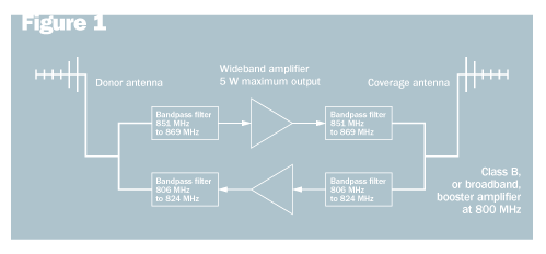
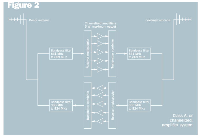
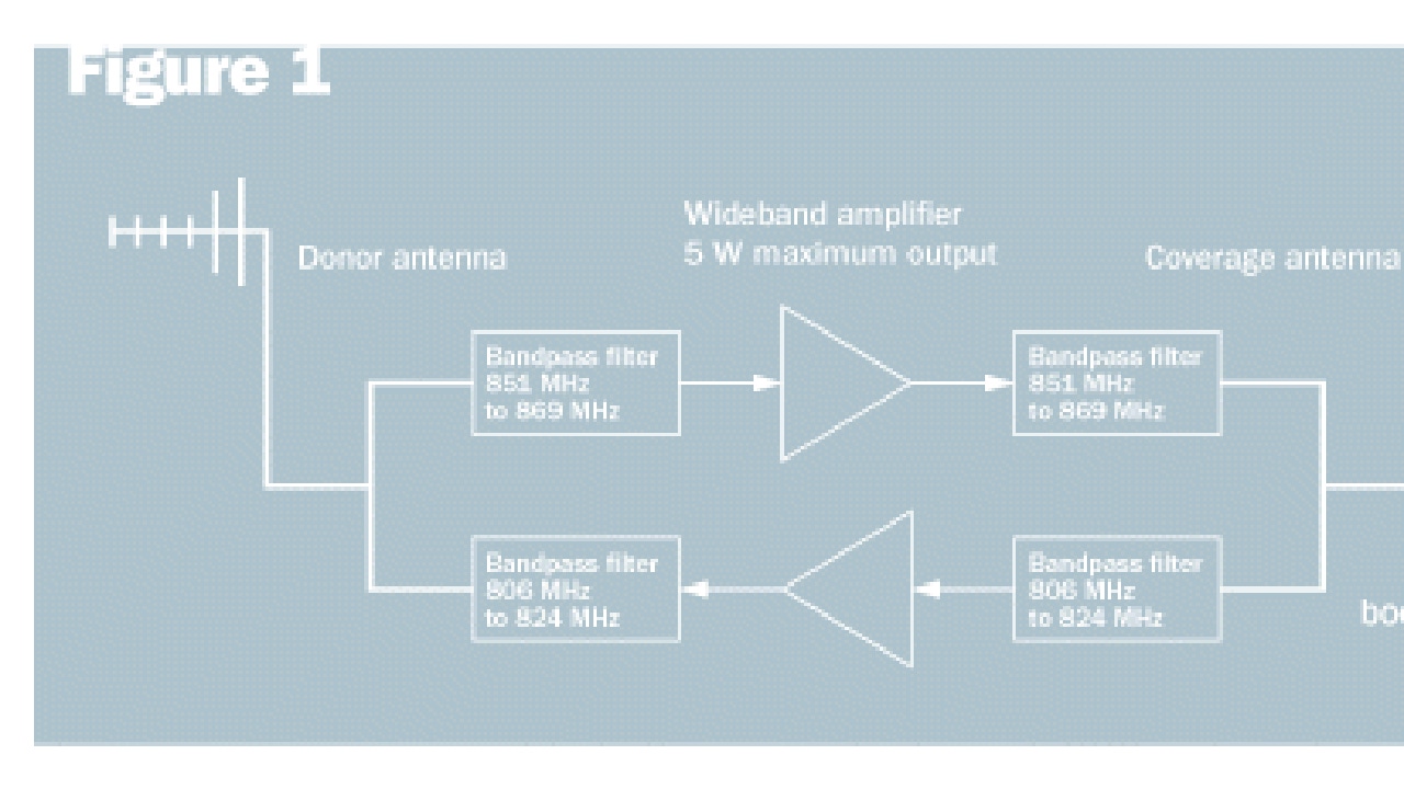
Broadband and channelized booster amplifiers are shown in Figures 1 and 2, respectively. The following are some of the advantages and limitations of each type of booster amplifier.
Broadband amplifiers:
Less expensive than channelized amplifiers.
Less group delay (wider filters), so less chance of delay-spread problems.
Practical power limitation means low power per channel for multi-channel systems.
Because it is broadband, it amplifies nearby ESMR and Cellular A Band signals, robbing the licensee’s channels of power and creating the potential for co-channel interference to ESMR and cellular subscribers in the immediate area.
Potential for harmful IM products in public-safety, SMR or cellular bands.
Channelized amplifiers:
Depending on vendor, can have greater power per channel for multi-channel systems
Greater adjacent channel isolation
Less interference to other cellular and public-safety systems
Fewer FCC limitations on where they can be used
More expensive because one amplifier is required for each channel
Large group delay causes delay spread in overlap areas. Typical group delay is 60 to 120 microseconds. Symbol period on a 9600 bits per second FSK control channel is 104.2 microseconds, so this is a genuine problem.
Now let’s consider the more modern solution to the indoor coverage problem: the DAS.
Distributed antenna system really is a generic term that includes all distributed amplifier systems, but the term recently has been associated with modern amplifier systems that use fiber-optic cable and CAT-5/6 twisted-pair cable to distribute wireless signals inside buildings. To understand the advantages of these modern systems, it helps to first understand the disadvantages of the traditional booster amplifier, also known as the bidirectional amplifier (BDA).
A traditional BDA is shown in Figure 3. Such a system uses a single amplifier in each direction (collectively the BDA) and distributes the signal using coaxial cable and either discrete antennas or radiating cable, or both. The big problem with the traditional BDA is the large amount of large diameter coaxial cable that is required. Relative to fiber and CAT-5, this cable is expensive, heavy, and requires special skills to install. Typically, the building infrastructure is not equipped to handle this specialized cable and the installation cost tends to be high.
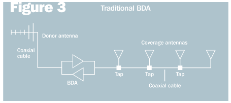
Another problem with the traditional BDA is that relatively high losses on coaxial cable at 800 and 1900 MHz require additional amplifiers downstream. Each amplifier in series further limits the dynamic range of the system, making it more likely that a user will overdrive the system, or that a user in a weak area will not be able to overcome thermal noise in the uplink due to a high noise figure.
The alternative to the traditional BDA is the modern DAS, which uses fiber-optic cable and CAT-5/6 twisted-pair cable. A typical architecture for such a DAS is shown in Figure 4.
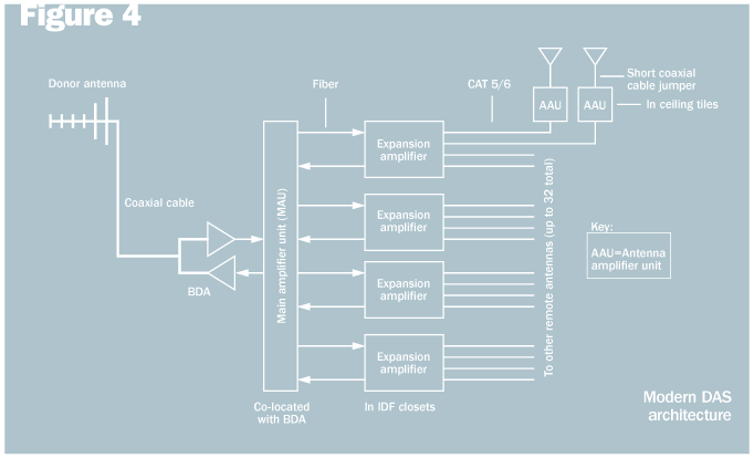
Note from Figure 4 that a BD still is required to boost the signal to a level acceptable to the main amplifier unit (MAU) if an over-the-air donor antenna is used. If the MAU is co-located with the cellular operator’s base station radio, a BDA is not needed and the operator simply dedicates one sector to the DAS. Fiber-optic cable is used to distribute the signal over the relatively long distance between the MAU and the expansion amplifier, which is located in an intermediate distribution frame (IDF) closet. Fiber is preferred because typical loss is less than 1 dB per mile, versus 1 dB per 100 feet for 7/8-inch diameter coaxial cable. There is a tradeoff, however. Fiber amplifiers are noisy and result in a relatively high noise figure on the uplink.
At the expansion amplifier, the signal is down-converted to the VHF band to limit losses over the CAT-5/6 twisted-pair cable. At the antenna amplifier unit (AAU), the signal is up-converted back to the original radio frequency. The small AAU is powered over the CAT-5/6 cable and is located in the ceiling tile, only a few feet from the antenna. On the uplink, the signal is down-converted at the AAU, passed over the CAT-5/6 cable, and up-converted at the expansion amplifier.
At this point, the reader might assume that the modern DAS operates on analog signals, which is true in many cases. However, at least one company markets a DAS that is all-digital but still uses an architecture similar to that depicted in Figure 4. One advantage of this digital DAS is that the signal is regenerated at each amplifier. Thus, there is no loss in signal quality provided the signal-to-noise ratio is adequate at each amplifier. However, it should be noted that a digital DAS introduces several technology challenges, including difficulty in achieving high dynamic range.


