Taking control of Project 25 systems
Test and evaluation of control channels is the key to solving the interoperability puzzle
November 1, 2004

Protocol is a crucial factor in achieving interoperability between mobile and portable digital radios operating on APCO Project 25-compliant networks. Equally important are test solutions that effectively log and analyze control messages to determine system compatibility.
The traffic and control channel features for both conventional and trunked P25 systems are not specific to any one P25 manufacturer or P25 radio frequency subsystem (RFSS) configuration. All mobiles supporting P25 formats should be able to access any P25 network as specified in the TIA/EIA-102 standard, which defines the operation of P25 systems. As radio systems continue to move from analog to digital, an understanding of how the control channels operate will help communications technicians ensure interoperability with new P25 systems.
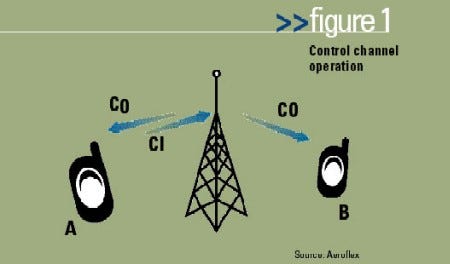
In the P25 standard, control channel operation maintains compatibility between conventional operations in that the modulation format and the bit rate are the same. In the P25 standard, the control channel and the traffic channel is a 9600 b/s channel using C4FM modulation to impart the digital 1s and 0s to the receiving radio. Trunked operations use packet-access techniques and require a registration process to coordinate user access, while the conventional version permits users to control their own access. Figure 1 provides an example of how a control channel operates.

As illustrated, the repeater is transmitting over an outbound control channel (CO) that both mobiles are monitoring. The outbound control channel sends information in “packets” called outbound signaling packets (OSPs).
Assume that mobile A wants to place a call to another user on the system. It transmits a request to the repeater on an inbound control channel (CI) using inbound signaling packets (ISPs). The repeater station and network process the request and then send an alert on the outbound control channel that the designated user, mobile B, recognizes as part of its group or as a signal designated specifically for itself.

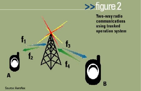
As shown in Figure 2, the calls are then assigned to particular traffic channels that operate on separate frequencies (f1, f2, f3, f4). The transmit and receive frequencies for the mobiles are offset from each other (f1 and f2) (f3 and f4) using a duplex offset. In the 800 MHz band, the offset is 45 MHz. Control of these resources is accomplished through the control channel that the mobile unit monitors continuously when not engaged in a communication session with another user or with the network. When it is engaged in communication, link control octet (LCO) messages ride along with the voice data on the traffic channel to control the communications link.
The ability to capture and save over-the-air control channel messages provides unique testing capabilities in P25 systems, including:
Verification that specific messages are being generated correctly from the P25 RFSS infrastructure:
Verification of encryption:
Field troubleshooting of radio interoperability problems:
By providing the ability to log a control channel, design engineers and technicians can capture a suspect control channel in one location. It can then be analyzed in a lab environment to see how radios are responding to some of the message elements and to compare various control channel implementations.
The P25 control channel messages are provided in two formats: single- and multi-block trunking signaling blocks (TSBKs). Most of the control channel information is sent via the single-block TSBK, with the multi-block TSBKs reserved for messaging that requires more extensive information. Figure 3 defines the single-block TSBK formats.
There are two multi-block formats. One uses the normal unconfirmed data header (UDH) format, with a special service access point (SAP) identifier in the header that causes the message to be processed as multi-block trunking information.
The other type is very similar, except that the header contains additional information that includes embedded operations codes and trunking-specific parameters for use in the multi-block TSBK. System implementation and the type of messages sent will determine which of these message formats should be used. Figure 4 defines the multi-block TSBK formats.
The TIA/EIA-102 standard defines several control channel messages, both in the multi-block and single-block formats. These can be broken down into three primary messaging groups: voice service, data service and control-and-status OSPs.
Voice service messages deal with the transactions, or messaging, sent between the control channel and the user to establish voice communications. Data service messages act much in the same manner to support data calls. However, the majority of the control channel signaling occurs for control-and-status information, which is critical to both the subscriber (user) and the system infrastructure because it sets up communication parameters before voice or data communications can occur.
To gain a full knowledge of the system operation, it is desirable to log both the OSP and ISP messages to compare how the mobiles and network operate together. Logging the LCO messages that accompany the voice or data information also is beneficial, particularly when the radios are used in a conventional repeater application.
A communications engineer can easily log control channel messages by utilizing a P25 test system (such as Aeroflex’s IFR 2975). When the receiver has been tuned to the proper frequency, such a test system will “listen” for various messages coming through. The system matrix allows the user to determine what messages to log and at what level. The system also can log the raw C4FM symbols before any error correction, the octets after error correction or the actual messages decoded with the actual message elements.
Once the receiver is tuned to the proper frequency, the test system will automatically decode and log the messages based on how the matrix is set up. Since the unit has only one receiver, only one type of message can be decoded at any one time. The system will then log the messages to a file on the unit’s internal hard drive and will display the sequence of messages received with a time stamp.
As can be seen by the above steps in utilizing an advanced P25 test system, engineers and technicians can quickly ascertain interoperability problems and other problems associated with control channel implementations to assist in the design and field test of P25 systems.
Rob Barden is senior product marketing manager for the radio test set line at Aeroflex’s Wichita, Kan., headquarters. He is a 22-year veteran of the test and measurement industry and graduated from Devry Institute in 1983.

_Michael_Burrell_Alamy[1].jpg?width=700&auto=webp&quality=80&disable=upscale)

