https://urgentcomm.com/wp-content/themes/ucm_child/assets/images/logo/footer-new-logo.png
  • Home
  • News
  • Multimedia
    • Back
    • Multimedia
    • Video
    • Podcasts
    • Galleries
  • Commentary
    • Back
    • Commentary
    • Urgent Matters
    • View From The Top
    • All Things IWCE
    • Legal Matters
  • Resources
    • Back
    • Resources
    • Webinars
    • White Papers
    • Reprints & Reuse
  • IWCE
    • Back
    • IWCE
    • Conference
    • Special Events
    • Exhibitor Listings
    • Premier Partners
    • Floor Plan
    • Exhibiting Information
    • Register for IWCE
  • About Us
    • Back
    • About Us
    • Contact Us
    • Advertise
    • Terms of Service
    • Privacy Statement
    • Cookies Policy
  • Related Sites
    • Back
    • American City & County
    • IWCE
    • Light Reading
    • IOT World Today
    • Mission Critical Technologies
    • Microwave/RF
    • T&D World
    • TU-Auto
  • In the field
    • Back
    • In the field
    • Broadband Push-to-X
    • Internet of Things
    • Project 25
    • Public-Safety Broadband/FirstNet
    • Virtual/Augmented Reality
    • Land Mobile Radio
    • Long Term Evolution (LTE)
    • Applications
    • Drones/Robots
    • IoT/Smart X
    • Software
    • Subscriber Devices
    • Video
  • Call Center/Command
    • Back
    • Call Center/Command
    • Artificial Intelligence
    • NG911
    • Alerting Systems
    • Analytics
    • Dispatch/Call-taking
    • Incident Command/Situational Awareness
    • Tracking, Monitoring & Control
  • Network Tech
    • Back
    • Network Tech
    • Interoperability
    • LMR 100
    • LMR 200
    • Backhaul
    • Deployables
    • Power
    • Tower & Site
    • Wireless Networks
    • Coverage/Interference
    • Security
    • System Design
    • System Installation
    • System Operation
    • Test & Measurement
  • Operations
    • Back
    • Operations
    • Critical Infrastructure
    • Enterprise
    • Federal Government/Military
    • Public Safety
    • State & Local Government
    • Training
  • Regulations
    • Back
    • Regulations
    • Narrowbanding
    • T-Band
    • Rebanding
    • TV White Spaces
    • None
    • Funding
    • Policy
    • Regional Coordination
    • Standards
  • Organizations
    • Back
    • Organizations
    • AASHTO
    • APCO
    • DHS
    • DMR Association
    • ETA
    • EWA
    • FCC
    • IWCE
    • NASEMSO
    • NATE
    • NXDN Forum
    • NENA
    • NIST/PSCR
    • NPSTC
    • NTIA/FirstNet
    • P25 TIG
    • TETRA + CCA
    • UTC
Urgent Communications
  • NEWSLETTER
  • Home
  • News
  • Multimedia
    • Back
    • Video
    • Podcasts
    • Omdia Crit Comms Circle Podcast
    • Galleries
    • IWCE’s Video Showcase
  • Commentary
    • Back
    • All Things IWCE
    • Urgent Matters
    • View From The Top
    • Legal Matters
  • Resources
    • Back
    • Webinars
    • White Papers
    • Reprints & Reuse
    • UC eZines
    • Sponsored content
  • IWCE
    • Back
    • Conference
    • Why Attend
    • Exhibitor Listing
    • Floor Plan
    • Exhibiting Information
    • Join the Event Mailing List
  • About Us
    • Back
    • About Us
    • Contact Us
    • Advertise
    • Terms of Service
    • Privacy Statement
    • Cookies Policy
  • Related Sites
    • Back
    • American City & County
    • IWCE
    • Light Reading
    • IOT World Today
    • TU-Auto
  • newsletter
  • In the field
    • Back
    • Internet of Things
    • Broadband Push-to-X
    • Project 25
    • Public-Safety Broadband/FirstNet
    • Virtual/Augmented Reality
    • Land Mobile Radio
    • Long Term Evolution (LTE)
    • Applications
    • Drones/Robots
    • IoT/Smart X
    • Software
    • Subscriber Devices
    • Video
  • Call Center/Command
    • Back
    • Artificial Intelligence
    • NG911
    • Alerting Systems
    • Analytics
    • Dispatch/Call-taking
    • Incident Command/Situational Awareness
    • Tracking, Monitoring & Control
  • Network Tech
    • Back
    • Cybersecurity
    • Interoperability
    • LMR 100
    • LMR 200
    • Backhaul
    • Deployables
    • Power
    • Tower & Site
    • Wireless Networks
    • Coverage/Interference
    • Security
    • System Design
    • System Installation
    • System Operation
    • Test & Measurement
  • Operations
    • Back
    • Critical Infrastructure
    • Enterprise
    • Federal Government/Military
    • Public Safety
    • State & Local Government
    • Training
  • Regulations
    • Back
    • Narrowbanding
    • T-Band
    • Rebanding
    • TV White Spaces
    • None
    • Funding
    • Policy
    • Regional Coordination
    • Standards
  • Organizations
    • Back
    • AASHTO
    • APCO
    • DHS
    • DMR Association
    • ETA
    • EWA
    • FCC
    • IWCE
    • NASEMSO
    • NATE
    • NXDN Forum
    • NENA
    • NIST/PSCR
    • NPSTC
    • NTIA/FirstNet
    • P25 TIG
    • TETRA + CCA
    • UTC
acc.com

Wireless Networks


A look at the PIN diode antenna switch

A look at the PIN diode antenna switch

It handles large power levels with minimum distortion, good isolation and low insertion loss.
  • Written by Urgent Communications Administrator
  • 1st July 2011

Whatever happened to the old electromechanical antenna relay? In most modern transceivers it has been replaced by the solid-state antenna changeover switch. However, as a ham-radio hobbyist, I still use an old electromechanical relay for the antenna changeover switch. This removes the antenna connection from my receiver and connects the antenna to my transmitter. In other words, the receiver and transmitter are separate units instead of combined to create a transceiver. There is a very audible click from the relay when the transmit switch is turned on or push-to-talk is pressed.

Electromechanical relays are fairly reliable but, due to their mechanical nature, they do have problems from time to time. Contacts become dirty and/or pitted from use and require cleaning. Of course, anything with moving parts wears with repetitive use. The special contact surface on relays eventually will wear down, causing an increase in the contact resistance. This causes higher insertion loss and will generate heat in the presence of high current. This heat will exacerbate the problem further and eventually the contacts are so worn that they present a high insertion loss to the signal.

Enter the PIN diode, which is a specially constructed type of diode designed for use as an electronic RF switch. In a typical diode, the P-N (positive-negative) junction consists of the P-material on one side and the N-material on the other. In the PIN diode construction, however, the P-material and N-material are separated by an intrinsic semiconductor material — hence the name positive-intrinsic-negative, or PIN, diode. This intrinsic semiconductor material reduces the capacitance at the junction, allowing the diode to be used at higher frequencies. The PIN diode behaves with low resistance when forward bias is applied and with high resistance when reverse bias is applied. A high forward bias can reduce the resistance of the PIN diode to less than 1 ohm. Similarly, a high reverse bias can increase the resistance to more than 10,000 ohms.

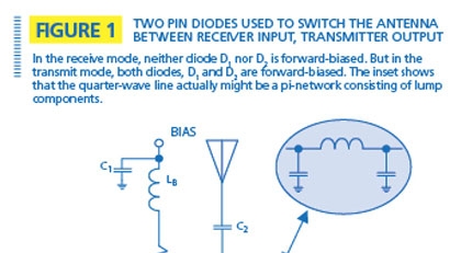
This article isn’t so much about how the PIN diode is constructed as it is about how this component is used in practical transceivers. Figure 1 shows a simple arrangement where two PIN diodes are used to switch the antenna between the receiver input and the transmitter output. In the receive mode, neither diode D1 nor D2 is forward biased. But in the transmit mode, both diodes, D1 and D2 are forward-biased. When D1 is forward-biased, the resistance of the diode is just a few tenths of an ohm, which allows the RF from the transmitter to pass with little insertion loss. With D2 forward-biased, the input to the receiver is virtually short-circuited. With this short circuit on the receiver side of the quarter-wave line, the antenna side of the quarter-wave line is characterized by high impedance (ideally, an open circuit). Hence, RF from the transmitter is routed to the antenna, but is blocked from the receiver.

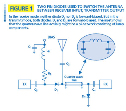
The inset in Figure 1 shows that the quarter-wave line actually might be a pi-network consisting of lump components. Often, the inductor is an etched inductor rather than a lump component. At higher frequencies, the entire transmission line might be an etched microstrip line. In the case of the quarter-wave line, the second harmonic would experience a low impedance to ground (ideally, a short circuit) and would be attenuated greatly, as would all even harmonics of the transmit frequency. In the case of the pi-network, it serves as a low pass filter, attenuating harmonics of the transmit frequency.

One of the disadvantages of the circuit in Figure 1 is that the quarter-wave line is a frequency-sensitive element. This means that the circuit operates properly over a relatively narrow frequency range.

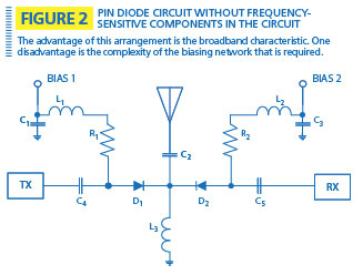
Figure 2 shows another circuit using PIN diodes that will operate properly over a wide frequency range. This is because there are no frequency-sensitive components in the circuit. In the transmit mode, PIN diode D1 is forward-biased, which creates a low-impedance path for the transmitter RF signal to pass to the antenna. At the same time, PIN diode D2 is reverse-biased to provide isolation between the receiver input and the antenna connection. In the receive mode, the situation is reversed. PIN diode D2 is forward-biased, which creates a low-impedance path between the antenna and the receiver input. At the same time, PIN diode D1 is reverse-biased, which isolates the antenna from the transmitter output. The advantage of this arrangement is the broadband characteristic. One disadvantage is the complexity of the biasing network that is required.

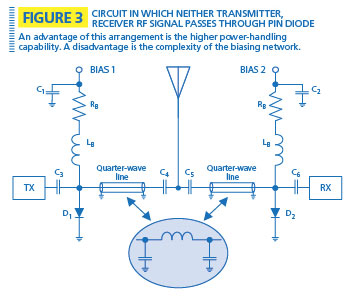
Yet another PIN diode antenna switch is shown in Figure 3. In this arrangement, neither the transmitter RF signal nor the receiver RF signal passes through a PIN diode. In the transmit mode, PIN diode D1 is reverse biased while PIN diode D2 is forward-biased. Thus, the transmitter output is not affected by PIN diode D1 because it is reverse biased, so the transmitter is connected directly to the antenna through the quarter-wave line (or pi-network, if used). Because PIN diode D2 is forward-biased, a short circuit is placed across the receiver input and, through the transformation process, the end connected to the antenna is at high impedance. In the receive mode, the situation is reversed — PIN diode D1 is forward-biased and D2 is reverse-biased. An advantage of this arrangement is the higher power-handling capability. A disadvantage is the complexity of the biasing network.

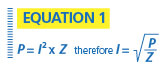
Refer back to Figure 1. The full RF current from the transmitter must flow through PIN diode D1. Suppose the power output from the transmitter is 30 W and that the antenna is perfectly matched producing a standing wave ratio, or SWR, of 1:1. This means that there is no reflected power from the antenna back toward the transmitter. Because power is equal to the square of the current multiplied by the impedance (50 ohms), we can compute the current by rearranging the formulas, as depicted in Equation 1.

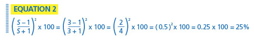
Because the power is 30 W and the impedance is 50 ohms, the RF current through PIN diode D1 is 0.775 amperes, or 775 milliamperes. This is for a perfectly matched antenna system. But, this doesn’t hold true if the antenna system is mismatched. Suppose the SWR is 3:1. This means that the percentage of reflected power is 25%. (See Equation 2.) Because the forward power was 30 W, 25% of this, or 7.5 watts, is reflected. The RF current in the reflected power would be amperes, or 387 milliamperes.

Assuming a worst-case scenario, where the forward and reverse currents add in phase, this means that the current through diode D1 is equal to 1162 mA, or 1.162 A (775 mA plus 387 mA). For the sake of simplifying the math let’s assume that the resistance of D1 (when forward biased) is 1 ohm. Under a perfectly matched-load condition, the power dissipation in D1 is watts. With a mismatched antenna with a SWR of 3:1, the power dissipation in D1 is watts — more than twice the dissipation under matched-load conditions. If a worst-case antenna mismatch exists, the reflected power would equal the forward power and (assuming the forward and reflected currents combine in phase) the current through D1 would double — and a doubling of current would mean a quadrupling of power dissipation in the diode. Thus, the power dissipation requirement of D1 would increase from 0.6 W under matched-load conditions to 2.4 W when the SWR is infinite. (This discussion assumes that the transmitter output power remains at 30 W under all mismatched conditions.)

Factors to be considered in the design of a PIN diode antenna switch are insertion loss, isolation between transmitter output and receiver input, distortion, bandwidth and power levels. High quality PIN diodes, when properly forward biased, can produce a very low resistance and, hence, low insertion loss. PIN diode antenna switches are capable of handling large power levels with minimum distortion, good isolation and low insertion loss. PIN diodes are used in many other applications, such as RF attenuators, AGC circuits and switching antenna elements to change the radiation pattern, and many other RF switching applications.

Harold Kinley is the author of three books, including Standard Radio Communications Manual and The Radioman’s Manual of RF Devices. A certified electronics technician, he holds an FCC First Class radio telephone license and an amateur radio operator Extra Class license.

Related Stories

  • RF switching with PIN diodes

Tags: Wireless Networks

Most Recent


  • Intelsat, OneWeb team on in-flight connectivity
    UK-government backed OneWeb and US-based Intelsat are joining forces to offer in-flight connectivity services to airlines, combining the former’s low-Earth-orbit (LEO) satellite service with the latter’s geostationary (GEO) satellites to “harness the power of multi-orbit capabilities.” The companies said they expect the multi-orbit solution to be in service by 2024. Inflight connectivity is certainly an […]
  • What the 6 GHz band might mean to fixed-wireless access
    Fixed-wireless access (FWA) technology is gaining significant interest in the US market, as evidenced by T-Mobile and Verizon collectively adding 816,000 new FWA customers during the second quarter of this year, while Charter Communications and Comcast collectively lost around 21,000 broadband customers. Leichtman Research Group reported that, over the past year, the US broadband industry added a total […]
  • FirstNet PTT technical progress highlighted by AT&T at APCO 2022
    FirstNet PTT—the mission-critical-push-to-talk (MCPTT) service launched in 2020—continues to evolve with the development of much-anticipated features like LMR interoperability and broadcast technology that will support one-to-many calls, an AT&T official said during a presentation at the recent APCO 2022 event in Anaheim, Calif. FirstNet users can use numerous different push-to-talk (PTT) applications that leverage the […]
  • Researchers developing health-monitoring e-tattoo
    Stories of people embedding digital devices into their bodies are becoming increasingly common; with these digital implants capable of everything from aiding mobility to paying for products, unlocking doors and storing data. A team of researchers from the Korea Advanced Institute of Science and Technology have taken a similar concept and applied it to the […]

Leave a comment Cancel reply

To leave a comment login with your Urgent Comms account:

Log in with your Urgent Comms account

Or alternatively provide your name, email address below:

Your email address will not be published. Required fields are marked *

Related Content

  • The battle over connected cars drags on
  • UK officials revamp ESN plans again, target Airwave-to-LTE transition for end of 2026
  • PSCR: Dereck Orr highlights features of June 21-24 virtual event
  • FirstNet buildout on pace for March 2023 completion, AT&T official says

Commentary


LTE and liability: Why the fire service must move forward with digital incident command

  • 2
6th May 2022

Partnership and collaboration must be the foundation for emergency communications

18th April 2022

FirstNet success means no hypothetical ‘shots’ need to be fired, Swenson says

22nd February 2022
view all

Events


UC Ezines


IWCE 2019 Wrap Up

13th May 2019
view all

Twitter


UrgentComm

Intelsat, OneWeb team on in-flight connectivity dlvr.it/SWgYb2

15th August 2022
UrgentComm

Black Hat 2022: Adapting to the growing cyberthreat landscape dlvr.it/SWgF3Y

15th August 2022
UrgentComm

Diffusing the connected car’s ticking data-privacy timebomb dlvr.it/SWdCw2

14th August 2022
UrgentComm

Patch madness: Vendor bug advisories are broken, so broken dlvr.it/SWcvFR

14th August 2022
UrgentComm

What the 6 GHz band might mean to fixed-wireless access dlvr.it/SWctfk

14th August 2022
UrgentComm

FirstNet PTT technical progress highlighted by AT&T at APCO 2022 dlvr.it/SWZtNJ

13th August 2022
UrgentComm

Newscan: D.C. appeals court upholds FCC decision to share 5.9 GHz V2V spectrum with Wi-Fi dlvr.it/SWZQpx

13th August 2022
UrgentComm

Cisco confirms data breach, hacked files leaked dlvr.it/SWV8l9

12th August 2022

Newsletter

Sign up for UrgentComm’s newsletters to receive regular news and information updates about Communications and Technology.

Expert Commentary

Learn from experts about the latest technology in automation, machine-learning, big data and cybersecurity.

Business Media

Find the latest videos and media from the market leaders.

Media Kit and Advertising

Want to reach our digital and print audiences? Learn more here.

DISCOVER MORE FROM INFORMA TECH

  • American City & County
  • IWCE
  • Light Reading
  • IOT World Today
  • Mission Critical Technologies
  • TU-Auto

WORKING WITH US

  • About Us
  • Contact Us
  • Events
  • Careers

FOLLOW Urgent Comms ON SOCIAL

  • Privacy
  • CCPA: “Do Not Sell My Data”
  • Cookies Policy
  • Terms
Copyright © 2022 Informa PLC. Informa PLC is registered in England and Wales with company number 8860726 whose registered and Head office is 5 Howick Place, London, SW1P 1WG.
This website uses cookies, including third party ones, to allow for analysis of how people use our website in order to improve your experience and our services. By continuing to use our website, you agree to the use of such cookies. Click here for more information on our Cookie Policy and Privacy Policy.
X