More simulcast optimization steps
TDI and Tradeoffs of Antenna Pattern, Site Location and Time Delay
TDI occurs when two or more simulcast signals arrive at the user’s radio antenna with comparable amplitude and relatively large delay. Both conditions must occur for TDI to be a problem.
If one site dominates, the carrier-to-interference ratio (C/I) is sufficient to overcome the delayed signal, no matter how long the delay. Conversely, if the two signal amplitudes are comparable and the C/I is low, only short delays are tolerable.
To control TDI in simulcast networks, it often is necessary to use directional antennas, so that only one site dominates in regions of long delays. But directional antennas only should be used when necessary, because a repeater site is a major investment. If a 90-degree beamwidth antenna is required to control TDI, then the site is providing only one-quarter of its potential coverage, but it costs the same as an omnidirectional site.
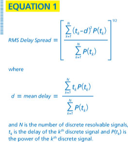 TDI is a function of both the interferer amplitude and delay. For most receivers, a sufficient figure of merit is the RMS (root mean square) delay spread, which is a weighted average of multiple overlapping signals that takes into account the delay and amplitude of each signal. The expression for RMS delay spread is given by Equation 1.
When purchasing a simulcast system, the customer should request measured simulcast delay spread performance from the manufacturer — information that rarely appears on equipment data sheets.
Maximum allowable delay spread is usually in the range of 25%-40% of a symbol period, but receiver implementations are vendor-dependent, so there is no universal rule of thumb. Note that, in addition to the relatively constant simulcast delay spread, there is a shorter, rapidly-changing delay spread caused by multipath fading. This is a subject for another day.
It is not enough to simply specify a maximum RMS delay spread, because it may be impractical to achieve throughout the service area. Instead, it is desirable to specify: (1) areas where higher delay spread can be tolerated, e.g., unpopulated areas far from roads; (2) a maximum percentage of the service area where higher delay spread is allowed; or (3) a combination of these two.
When designing a simulcast network, the engineer first uses a computer propagation model or drive-test measurements to predict the coverage from each candidate site. Larger networks rarely are technically feasible, if all repeater sites employ omnidirectional transmit antennas. In such situations, directional antennas must be used.
The number of possible combinations of site delays and antenna patterns can be in the thousands, and even modern computers cannot model all possible combinations in the designer’s lifetime. Consequently, the designer may resort to rules of thumb.
One common rule of thumb is to employ an omnidirectional antenna at a single central site (usually the tallest site, to get the most bang for the buck) and employ directional antennas at the surrounding sites pointing away from the central site. This makes control of TDI easier and more predictable.
However, once the antenna patterns are chosen, other more effective combinations may be missed. For instance, it may be possible for two or more sites to employ omnidirectional antennas without causing harmful TDI in the service area, but these options may be overlooked because the rule of thumb was applied too soon.
To arrive at the optimal solution (meeting coverage requirement with the least number of sites), a good software tool is needed to test multiple dimensions: repeater site locations, antenna patterns, and site delay settings. Software tools with these capabilities exist but are not common. Usually, some combination of manual tweaking and computer iteration is necessary.
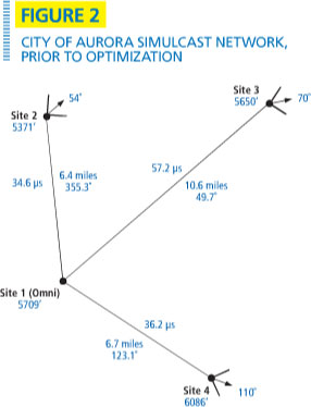 An example of a simulcast optimization problem is the four-site 800 MHz trunked radio network operated by the city of Aurora, Colo. Figure 2 depicts the time delays and antenna patterns that existed before optimization. During the optimization process, each directional antenna site was replaced with omnidirectional antennas, and the set of site time delays was iterated to find the minimum number of coverage tiles with excessive TDI.
Directional antennas then were reintroduced manually with various azimuths, and the process was repeated. In the end, it was found that Site 2 could employ an omnidirectional antenna, but Sites 3 and 4 needed to retain their directional patterns. As a result, coverage improved significantly to the west and south of Site 2 — areas where improved service was badly needed.
Jay Jacobsmeyer, KD0OFB, is President of Pericle Communications Company, a consulting engineering firm located in Colorado Springs, Colo. He holds BS and MS degrees in Electrical Engineering from Virginia Tech and Cornell University, respectively, and has more than 30 years experience as a radio frequency engineer.