https://urgentcomm.com/wp-content/themes/ucm_child/assets/images/logo/footer-new-logo.png
  • Home
  • News
  • Multimedia
    • Back
    • Multimedia
    • Video
    • Podcasts
    • Galleries
  • Commentary
    • Back
    • Commentary
    • Urgent Matters
    • View From The Top
    • All Things IWCE
    • Legal Matters
  • Resources
    • Back
    • Resources
    • Webinars
    • White Papers
    • Reprints & Reuse
  • IWCE
    • Back
    • IWCE
    • Conference
    • Special Events
    • Exhibitor Listings
    • Premier Partners
    • Floor Plan
    • Exhibiting Information
    • Register for IWCE
  • About Us
    • Back
    • About Us
    • Contact Us
    • Advertise
    • Terms of Service
    • Privacy Statement
    • Cookies Policy
  • Related Sites
    • Back
    • American City & County
    • IWCE
    • Light Reading
    • IOT World Today
    • Mission Critical Technologies
    • Microwave/RF
    • T&D World
    • TU-Auto
  • In the field
    • Back
    • In the field
    • Broadband Push-to-X
    • Internet of Things
    • Project 25
    • Public-Safety Broadband/FirstNet
    • Virtual/Augmented Reality
    • Land Mobile Radio
    • Long Term Evolution (LTE)
    • Applications
    • Drones/Robots
    • IoT/Smart X
    • Software
    • Subscriber Devices
    • Video
  • Call Center/Command
    • Back
    • Call Center/Command
    • Artificial Intelligence
    • NG911
    • Alerting Systems
    • Analytics
    • Dispatch/Call-taking
    • Incident Command/Situational Awareness
    • Tracking, Monitoring & Control
  • Network Tech
    • Back
    • Network Tech
    • Interoperability
    • LMR 100
    • LMR 200
    • Backhaul
    • Deployables
    • Power
    • Tower & Site
    • Wireless Networks
    • Coverage/Interference
    • Security
    • System Design
    • System Installation
    • System Operation
    • Test & Measurement
  • Operations
    • Back
    • Operations
    • Critical Infrastructure
    • Enterprise
    • Federal Government/Military
    • Public Safety
    • State & Local Government
    • Training
  • Regulations
    • Back
    • Regulations
    • Narrowbanding
    • T-Band
    • Rebanding
    • TV White Spaces
    • None
    • Funding
    • Policy
    • Regional Coordination
    • Standards
  • Organizations
    • Back
    • Organizations
    • AASHTO
    • APCO
    • DHS
    • DMR Association
    • ETA
    • EWA
    • FCC
    • IWCE
    • NASEMSO
    • NATE
    • NXDN Forum
    • NENA
    • NIST/PSCR
    • NPSTC
    • NTIA/FirstNet
    • P25 TIG
    • TETRA + CCA
    • UTC
Urgent Communications
  • NEWSLETTER
  • Home
  • News
  • Multimedia
    • Back
    • Video
    • Podcasts
    • Omdia Crit Comms Circle Podcast
    • Galleries
    • IWCE’s Video Showcase
  • Commentary
    • Back
    • All Things IWCE
    • Urgent Matters
    • View From The Top
    • Legal Matters
  • Resources
    • Back
    • Webinars
    • White Papers
    • Reprints & Reuse
    • UC eZines
    • Sponsored content
  • IWCE
    • Back
    • Conference
    • Why Attend
    • Exhibitor Listing
    • Floor Plan
    • Exhibiting Information
    • Join the Event Mailing List
  • About Us
    • Back
    • About Us
    • Contact Us
    • Advertise
    • Terms of Service
    • Privacy Statement
    • Cookies Policy
  • Related Sites
    • Back
    • American City & County
    • IWCE
    • Light Reading
    • IOT World Today
    • TU-Auto
  • newsletter
  • In the field
    • Back
    • Internet of Things
    • Broadband Push-to-X
    • Project 25
    • Public-Safety Broadband/FirstNet
    • Virtual/Augmented Reality
    • Land Mobile Radio
    • Long Term Evolution (LTE)
    • Applications
    • Drones/Robots
    • IoT/Smart X
    • Software
    • Subscriber Devices
    • Video
  • Call Center/Command
    • Back
    • Artificial Intelligence
    • NG911
    • Alerting Systems
    • Analytics
    • Dispatch/Call-taking
    • Incident Command/Situational Awareness
    • Tracking, Monitoring & Control
  • Network Tech
    • Back
    • Cybersecurity
    • Interoperability
    • LMR 100
    • LMR 200
    • Backhaul
    • Deployables
    • Power
    • Tower & Site
    • Wireless Networks
    • Coverage/Interference
    • Security
    • System Design
    • System Installation
    • System Operation
    • Test & Measurement
  • Operations
    • Back
    • Critical Infrastructure
    • Enterprise
    • Federal Government/Military
    • Public Safety
    • State & Local Government
    • Training
  • Regulations
    • Back
    • Narrowbanding
    • T-Band
    • Rebanding
    • TV White Spaces
    • None
    • Funding
    • Policy
    • Regional Coordination
    • Standards
  • Organizations
    • Back
    • AASHTO
    • APCO
    • DHS
    • DMR Association
    • ETA
    • EWA
    • FCC
    • IWCE
    • NASEMSO
    • NATE
    • NXDN Forum
    • NENA
    • NIST/PSCR
    • NPSTC
    • NTIA/FirstNet
    • P25 TIG
    • TETRA + CCA
    • UTC
acc.com

Test & Measurement


Demystifying RF attenuators

Demystifying RF attenuators

Creating a high-precision pad can be tricky--here's how to do it
  • Written by Urgent Communications Administrator
  • 1st November 2004

Many different small test accessories often are needed when performing radio frequency, or RF, test and measurement work. One such item is the RF attenuator, which typically consists of several individual “pads” that can be switched in or out to increase or decrease the total attenuation. (Generally, the word “pad” refers to a single fixed attenuator.) The RF attenuator is frequently used in many test and measurement procedures in radio communication; practical information on its construction and use is presented here.

Attenuators for audio frequencies are easily constructed out of ordinary resistors using a formula or chart to design the pad. However, RF represents a different ballgame. At high RFs, the design of the pad is much more stringent. Special resistors often are used to make a highly accurate pad. For example, a 6 dB pad might actually present 6 dB of attenuation at 1 MHz or lower but shows a significantly different attenuation at 150 MHz. If you are trying to make precise measurements, then high-precision attenuators are necessary.

Precision attenuators for RF applications are not cheap, and a variety of different attenuation levels often are needed; consequently, a well-equipped RF toolbox should contain a good variety of RF attenuators. Fixed attenuators of 3 dB, 6 dB and 10 dB are most often needed. RF attenuators are available with different RF connectors. Because of the quick connect/disconnect feature, the BNC connector is convenient for testing applications.

However, instead of BNC connectors, many RF devices feature UHF or Type N RF connectors. Unless you have the correct connector on the pad, RF adaptors will be required to make the transition from one type of connector to another. With the correct RF adaptor one can connect “anything to anything.” However, the liberal use of RF adaptors can lead to problems. If possible, it is best to use an RF pad with the proper RF connector for the particular application at hand. RF pads can be connected in a piggyback fashion to provide an attenuation equal to the sum of the individual pads. However, it is best to use a single pad with the proper attenuation, if possible.

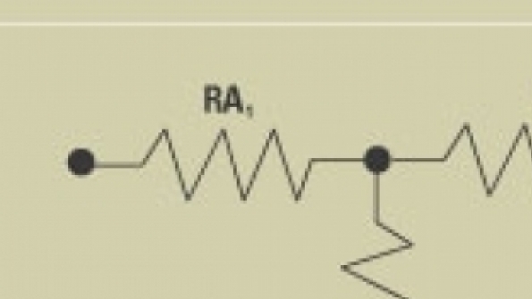
Step attenuators also are available in a variety of different attenuation levels and can be used to provide attenuation values ranging from 1 dB to 100 dB or more. Switches for step attenuators may be simple toggle switches, rocker switches, slide switches or push-button switches. By switching in the appropriate attenuators, the attenuation can be increased or decreased in 1 dB steps. Attenuators may be constructed in the “T” configuration (Figure 1) or the “pi” configuration (Figure 2).

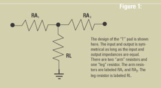
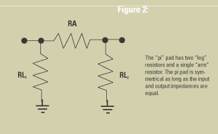
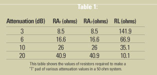
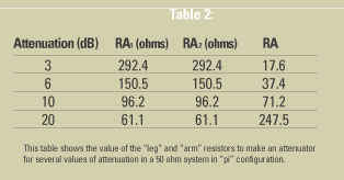
Table 1 shows the values of resistors used in the T pad for various attenuation values, while Table 2 shows the values of the resistors used in the pi pad for the same attenuation values. The attenuators are symmetrical, provided the input and output impedances are the same. In applications where attenuators are used as impedance-matching devices, they are not symmetrical.

Step attenuators are available in a variety of switching formats. They may be relay-programmable, TTL-programmable, GPIB-programmable and so on. No matter how the total attenuation is set, the principle is the same — individual pads equaling the total desired attenuation are switched into a cascade arrangement. The unused pads are simply bypassed by a straight-through connection.

Several different methods can be used to check the accuracy of an attenuator or a single pad. The simplest method is to use an ohmmeter to check the resistance. The resistance of an attenuator or pad designed for a 50 ohm system will show the same resistance on either side because they are of a symmetrical design. This is true whether the pad or attenuator is made in the T or pi configuration. This is not true of impedance-matching pads.

To determine the resistance that should be “seen” across the input or output of the pad or attenuator, you will need to know the resistance of the arm and leg resistors that make up the pad. The values of the arm and leg resistors for a few values of attenuation are shown in Table 1 for T pads and in Table 2 for pi pads. Using a 3 dB pi pad as an example, Table 2 shows that the arm resistor should be 17.6 ohms, and the leg resistors should be 292.4 ohms. Thus, the resistance seen across the input or output is 150.5 ohms. If a step attenuator is composed of pi pads, the test can be conducted with the 1 dB and 2 dB pads switched in and all others switched out. Or, just the 3 dB pad can be switched in, with all others out. The ohmmeter reading should be the same no matter how the 3 dB attenuation is obtained.

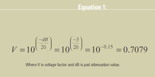
Another method that can be used is to connect a DC voltage of 1V across the input of the attenuator or pad (see Figure 3). For a 3 dB pad, the voltage appearing across the other side of the pad will be 0.708 volts. The voltage reduction factor can be determined by using the formula in Equation 1.

In Figure 3, 1 VDC is applied across the input to the 3 dB pad and 0.708 VDC is measured at the opposite side. It is important to note that a 50 ohm termination should be connected to the output side where the attenuated voltage is measured. If the measured voltage differs significantly from the calculated voltage, one or more of the resistors making up the pad has changed value.

While the two previous test procedures will reveal whether the resistors comprising the pad are of the correct value, the tests do not indicate the accuracy of the pad at RF frequencies. A couple of other methods can be used for the RF test.

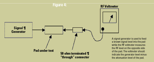
Figure 4 shows a signal generator connected to an attenuator on one side and a RF voltmeter connected to the opposite side through a 50 ohm terminated “through” connector. The signal generator is set to the desired test frequency and the output level adjusted to a convenient level, such as -20 dBm. With all of the attenuation switched out, the reference reading on the RF voltmeter indicates the insertion loss of the attenuator. This is noted as the reference mark.

Then, a level of attenuation is switched in, such as 3 dB. The RF voltmeter should drop by 3 dB. Increasing the signal generator output level by 3 dB should return the RF voltmeter reading to the reference mark obtained at the beginning of the test procedure. This test should be run at increasingly higher frequencies until a point is reached where the accuracy of the attenuator fails to meet the required accuracy. All attenuator levels should be checked at each frequency.

Another way to do the RF test is to use a spectrum analyzer that can be set for scale divisions low enough to check the lowest attenuation level to be checked. For example, to check an attenuator at 1 dB attenuation, the spectrum analyzer should be set to 0.25 dB/division. This means that an attenuation of 1 dB will change the displayed signal by 4 divisions.

Generally, the dB/division control is set to the least value that will give maximum change of the displayed signal without going off the screen. To check for 5 dB attenuation, the signal generator is adjusted to 0 dBm, and the spectrum analyzer level is set to produce a display at the top of the reference scale with the dB/division control set to 1 dB/div. Then, with the 5 dB attenuator switched in, the display should drop by 5 divisions. Increase the signal generator level by 5 dB to ensure that the display returns to the previous level. This test should be run at all the frequencies at which you plan to use the attenuator or pad.

Typical uses of pads include the “padding” of the signal generator output to make sure the signal generator always sees a 50 ohm load impedance. When testing bandpass or reject cavities, both sides of the cavity should be connected through a pad of 3 dB to 6 dB of attenuation. Inputs and outputs of amplifiers often are padded to ensure stable operation. Pads are used in many test and measurement procedures to ensure measurement accuracy.

An important point to remember, above all, is to never key a transmitter into the pad. Unless the pad is designed to handle the transmitter power, the pad could be damaged severely, rendering it useless. Proper handling and care of the pad or attenuator will yield many years of reliable service. Handle with care!

Tags: System Management Call Center/Command content System Design System Operation Test & Measurement Tower & Site

Most Recent


  • Hytera, Motorola Solutions refile appeal, cross-appeal in civil case
    As expected, Hytera Communications again has appealed a $543.7 million judgment against it to the 7th Circuit Court of Appeals, while Motorola Solutions this week filed for second time a cross appeal in the case that was initiated more than four years ago. There was little surprise in the filings, because both Hytera and Motorola […]
  • Amid shifting workplace expectations, local government employers must adapt
    Constrained by inflexible budgets, local government employers can’t compete with the lucrative salaries offered in the private sector. And while recruitment has always been a challenge for public employers, the last two years have been especially difficult. From January 2020 to the same month this year, government organizations lost around 600,000 jobs—more than manufacturing, wholesale […]
  • The private-wireless networking opportunity shouldn't stay too private
    Everyone is excited about the market for private wireless networking. And that’s no surprise: It affords all the companies that cut their teeth building big, public 4G and 5G networks the chance to leverage that work into the enterprise space – where margins might be much more attractive. Moreover, it could ultimately grow into a […]
  • Europe's first driverless-car test completed
    U.K. company Oxbotica has successfully completed Europe’s first trial of a fully autonomous vehicle with no occupants on public roads. The test took place in Oxbotica’s home city of Oxford and featured a new electric vehicle prototype, the AppliedEV – essentially a platform that previews future vehicles for the transportation sector – fitted with the firm’s Oxbotica Driver tech. […]

One comment

  1. Avatar Thomas Searcy 26th February 2014 @ 8:09 pm
    Reply

    Outstanding job on this
    Outstanding job on this explanation of attenuators in rf measurements. Thanks, Tom

Leave a comment Cancel reply

To leave a comment login with your Urgent Comms account:

Log in with your Urgent Comms account

Or alternatively provide your name, email address below:

Your email address will not be published. Required fields are marked *

Related Content

  • New Orleans-area 911 center inks multiyear APEX deal with Carbyne to replace call-handling system
  • Cyber is the new Cold War, and AI is the arms race
  • Microsoft patches 6 zero-day vulnerabilities under active attack
  • AI energizes remote monitoring of patients, fuels bidirectional health care

Commentary


LTE and liability: Why the fire service must move forward with digital incident command

  • 2
6th May 2022

Partnership and collaboration must be the foundation for emergency communications

18th April 2022

FirstNet success means no hypothetical ‘shots’ need to be fired, Swenson says

22nd February 2022
view all

Events


UC Ezines


IWCE 2019 Wrap Up

13th May 2019
view all

Twitter


UrgentComm

Hytera, Motorola Solutions refile appeal, cross-appeal in civil case dlvr.it/SQxNX1

24th May 2022
UrgentComm

Amid shifting workplace expectations, local government employers must adapt dlvr.it/SQwVVs

23rd May 2022
UrgentComm

The private-wireless networking opportunity shouldn’t stay too private dlvr.it/SQw7MT

23rd May 2022
UrgentComm

Europe’s first driverless-car test completed dlvr.it/SQvqyY

23rd May 2022
UrgentComm

FCC approves order to modernize priority-service rules dlvr.it/SQmSN0

20th May 2022
UrgentComm

Meet smart city goals cost-effectively dlvr.it/SQmPkr

20th May 2022
UrgentComm

Security for microwave links dlvr.it/SQmNwX

20th May 2022
UrgentComm

Florida P25 system slated for completion in 2024, will interoperate with FirstNet dlvr.it/SQm9cf

20th May 2022

Newsletter

Sign up for UrgentComm’s newsletters to receive regular news and information updates about Communications and Technology.

Expert Commentary

Learn from experts about the latest technology in automation, machine-learning, big data and cybersecurity.

Business Media

Find the latest videos and media from the market leaders.

Media Kit and Advertising

Want to reach our digital and print audiences? Learn more here.

DISCOVER MORE FROM INFORMA TECH

  • American City & County
  • IWCE
  • Light Reading
  • IOT World Today
  • Mission Critical Technologies
  • Microwave/RF
  • T&D World
  • TU-Auto

WORKING WITH US

  • About Us
  • Contact Us
  • Events
  • Careers

FOLLOW Urgent Comms ON SOCIAL

  • Privacy
  • CCPA: “Do Not Sell My Data”
  • Cookies Policy
  • Terms
Copyright © 2022 Informa PLC. Informa PLC is registered in England and Wales with company number 8860726 whose registered and Head office is 5 Howick Place, London, SW1P 1WG.
This website uses cookies, including third party ones, to allow for analysis of how people use our website in order to improve your experience and our services. By continuing to use our website, you agree to the use of such cookies. Click here for more information on our Cookie Policy and Privacy Policy.
X