https://urgentcomm.com/wp-content/themes/ucm_child/assets/images/logo/footer-new-logo.png
  • Home
  • News
  • Multimedia
    • Back
    • Multimedia
    • Video
    • Podcasts
    • Galleries
    • IWCE’s Video Showcase
    • Product Guides
  • Commentary
    • Back
    • Commentary
    • Urgent Matters
    • View From The Top
    • All Things IWCE
    • Legal Matters
  • Resources
    • Back
    • Resources
    • Webinars
    • White Papers
    • Reprints & Reuse
  • IWCE
    • Back
    • IWCE
    • Conference
    • Special Events
    • Exhibitor Listings
    • Premier Partners
    • Floor Plan
    • Exhibiting Information
    • Register for IWCE
  • About Us
    • Back
    • About Us
    • Contact Us
    • Advertise
    • Terms of Service
    • Privacy Statement
    • Cookie Policy
  • Related Sites
    • Back
    • American City & County
    • IWCE
    • Light Reading
    • IOT World Today
    • Mission Critical Technologies
    • TU-Auto
  • In the field
    • Back
    • In the field
    • Broadband Push-to-X
    • Internet of Things
    • Project 25
    • Public-Safety Broadband/FirstNet
    • Virtual/Augmented Reality
    • Land Mobile Radio
    • Long Term Evolution (LTE)
    • Applications
    • Drones/Robots
    • IoT/Smart X
    • Software
    • Subscriber Devices
    • Video
  • Call Center/Command
    • Back
    • Call Center/Command
    • Artificial Intelligence
    • NG911
    • Alerting Systems
    • Analytics
    • Dispatch/Call-taking
    • Incident Command/Situational Awareness
    • Tracking, Monitoring & Control
  • Network Tech
    • Back
    • Network Tech
    • Interoperability
    • LMR 100
    • LMR 200
    • Backhaul
    • Deployables
    • Power
    • Tower & Site
    • Wireless Networks
    • Coverage/Interference
    • Security
    • System Design
    • System Installation
    • System Operation
    • Test & Measurement
  • Operations
    • Back
    • Operations
    • Critical Infrastructure
    • Enterprise
    • Federal Government/Military
    • Public Safety
    • State & Local Government
    • Training
  • Regulations
    • Back
    • Regulations
    • Narrowbanding
    • T-Band
    • Rebanding
    • TV White Spaces
    • None
    • Funding
    • Policy
    • Regional Coordination
    • Standards
  • Organizations
    • Back
    • Organizations
    • AASHTO
    • APCO
    • DHS
    • DMR Association
    • ETA
    • EWA
    • FCC
    • IWCE
    • NASEMSO
    • NATE
    • NXDN Forum
    • NENA
    • NIST/PSCR
    • NPSTC
    • NTIA/FirstNet
    • P25 TIG
    • TETRA + CCA
    • UTC
Urgent Communications
  • NEWSLETTER
  • Home
  • News
  • Multimedia
    • Back
    • Video
    • Podcasts
    • Omdia Crit Comms Circle Podcast
    • Galleries
    • IWCE’s Video Showcase
    • Product Guides
  • Commentary
    • Back
    • All Things IWCE
    • Urgent Matters
    • View From The Top
    • Legal Matters
  • Resources
    • Back
    • Webinars
    • White Papers
    • Reprints & Reuse
    • UC eZines
    • Sponsored content
  • IWCE
    • Back
    • Conference
    • Why Attend
    • Exhibitor Listing
    • Floor Plan
    • Exhibiting Information
    • Join the Event Mailing List
  • About Us
    • Back
    • About Us
    • Contact Us
    • Advertise
    • Cookie Policy
    • Terms of Service
    • Privacy Statement
  • Related Sites
    • Back
    • American City & County
    • IWCE
    • Light Reading
    • IOT World Today
    • TU-Auto
  • newsletter
  • In the field
    • Back
    • Internet of Things
    • Broadband Push-to-X
    • Project 25
    • Public-Safety Broadband/FirstNet
    • Virtual/Augmented Reality
    • Land Mobile Radio
    • Long Term Evolution (LTE)
    • Applications
    • Drones/Robots
    • IoT/Smart X
    • Software
    • Subscriber Devices
    • Video
  • Call Center/Command
    • Back
    • Artificial Intelligence
    • NG911
    • Alerting Systems
    • Analytics
    • Dispatch/Call-taking
    • Incident Command/Situational Awareness
    • Tracking, Monitoring & Control
  • Network Tech
    • Back
    • Cybersecurity
    • Interoperability
    • LMR 100
    • LMR 200
    • Backhaul
    • Deployables
    • Power
    • Tower & Site
    • Wireless Networks
    • Coverage/Interference
    • Security
    • System Design
    • System Installation
    • System Operation
    • Test & Measurement
  • Operations
    • Back
    • Critical Infrastructure
    • Enterprise
    • Federal Government/Military
    • Public Safety
    • State & Local Government
    • Training
  • Regulations
    • Back
    • Narrowbanding
    • T-Band
    • Rebanding
    • TV White Spaces
    • None
    • Funding
    • Policy
    • Regional Coordination
    • Standards
  • Organizations
    • Back
    • AASHTO
    • APCO
    • DHS
    • DMR Association
    • ETA
    • EWA
    • FCC
    • IWCE
    • NASEMSO
    • NATE
    • NXDN Forum
    • NENA
    • NIST/PSCR
    • NPSTC
    • NTIA/FirstNet
    • P25 TIG
    • TETRA + CCA
    • UTC
acc.com

Call Center/Command


Deciphering RF units of measure

Deciphering RF units of measure

It is imperative that wireless communication technicians understand the various units of measurement used to quantify the level or amplitude of a radio
  • Written by Urgent Communications Administrator
  • 1st December 2006

It is imperative that wireless communication technicians understand the various units of measurement used to quantify the level or amplitude of a radio frequency, or RF, signal. This article will describe the relationship between several of the more frequently used units of measure and how they are applied in practice.

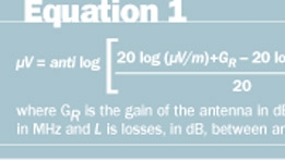
Suppose the sensitivity of a voice pager is given as 25 µV/m (microvolts per meter) in terms of field strength, or 0.5 µV chassis sensitivity, at a frequency of 160 MHz. From this information, we can determine the amount of gain of the internal antenna in dBd [gain of antenna referenced to a half-wave (λ/2) dipole]. First, we must know how many microvolts would appear across the terminals of a half-wave dipole when placed in a field strength of 25 µV/m. Since we are using a half-wave dipole, GR is equal to 0. The loss (L) is assumed to be 0 dB. Equation 1 provides the formula for calculating microvolts (µV) from microvolts-per-meter (µV/m).

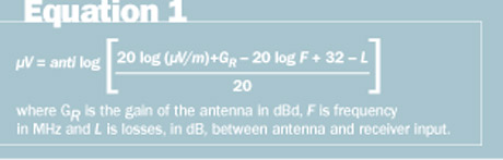
Plugging the given figures into Equation 1 would yield 6.28 µV. Thus, a half-wave dipole in a field strength of 25 µV/m would produce 6.28 µV at the receiver input. According to the specifications, the chassis sensitivity of the pager is 0.5 µV. Thus, we can assume that a field strength of 25 µV/m would produce an input level of 0.5 µV at the pager input. Since a half-wave dipole would produce a level of 6.28 µV, the gain of the pager’s internal antenna can be determined as shown in Equation 2. Thus, the pager’s internal antenna has a gain of -22 dBd. However, a negative gain is actually a loss, so the pager’s internal antenna has a handicap of 22 dB compared with a half-wave dipole.

Testing pager sensitivity presents some difficulty because pager transmitters are very busy and produce very strong signals that can interfere with test results. In addition, many pagers don’t provide a direct input to the receiver for connection to a signal generator. Even if an RF input jack was provided, paging signals in the area might be strong enough to invalidate test results. Thus, the pager must be isolated from extraneous signals.

Generally, pagers are tested in a shielded RF test enclosure or TEM cell that provides a connection (RF jack) through which a signal is fed from a signal generator at a level that produces the required field strength at the pager antenna. Cell phones and other wireless devices are tested in a similar manner, because these types of transmitters are very busy and may produce high RF field strength levels in the test area. Well-shielded screen rooms often are used for testing such devices and must offer very high RF isolation at the frequencies used by the DUT (device under test).

In addition to microvolts-per-meter (µV/m), field strength is sometimes stated in terms of dBu or dBµV/m, which are interchangeable. In these terms, 1 µV/m is the reference for 0 dBu. Therefore, 6 dBu or 6 dBµV/m is equal to 2 µV/m because 2 µV/m is a doubling of the voltage, and doubling the voltage is an increase of 6 dB.

It also is important to determine the level of field strength at the antenna required to produce a given signal level (in microvolts) at the input of a receiver. For example, suppose we have a system operating on a frequency of 460 MHz and the desired signal level at the input of the receiver is 1 µV. The antenna has a gain of 6 dBd, and the cable loss is 2 dB. What field intensity at the antenna will produce 1 µV at the receiver input under these conditions? Equation 3 can be used to compute the required field intensity. Plugging in the values above yields 7.29 µ/m.

It is important to note that frequency is a factor in determining how many microvolts are produced across the antenna terminals from a given field intensity. For example, a field intensity of 20 µV/m will produce approximately 20 µV across the antenna terminals at 40 MHz (assuming a 0 dBd gain antenna).

At 160 MHz, a field intensity of 20 µV/m will produce approximately 5 µV across the antenna terminals (again, assuming 0 dBd antenna gain).

Notice that the signal level appearing across the antenna terminals is inversely proportional to the frequency. In this example, the frequency was multiplied by a factor of 4 while the signal level across the antenna terminals was divided by 4.

If the frequency had been changed to 20 MHz (half of 40 MHz), the signal level across the antenna terminals would have doubled to approximately 40 V. This has to do with the antenna factor, designated by K. At approximately 40 MHz the antenna factor (K) is approximately zero, assuming a 0 dBd gain antenna.

Signal generators often are calibrated in microvolts and dBm. Because the dBm is defined as 1 milliwatt (mW) in 50 , the voltage required to produce 1 mW in 50 is derived from Equation 4.

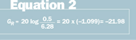
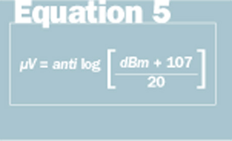
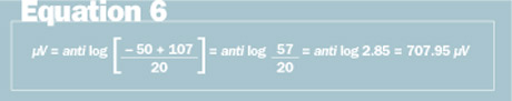
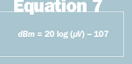
Thus, 0 dBm is 223,607 µV. You will also find wide usage of the unit dBµV, or decibels referenced to 1 µV. Hence, 1µV is 0 dBµV. As long as we know the reference value, it is relatively simple to calculate the RF level. For example, a value of -50 dBm can be converted to microvolts (µV) by using Equation 5. Plugging in the numbers above yields the result indicated in Equation 6 on page 38, while Equation 7 can be used to convert microvolts (µV) to dBm.

The term dBW also is used to quantify the amplitude of an RF signal. It is simple to convert dBm to dBW — just subtract 30 from the dBm figure to get dBW. That is: dBW=dBm-30. Conversely, dBm=dBW+30.

Often, RF power is stated in terms of dBm or dBW. It is easy to work with these values if we simply remember that 100 W is 50 dBm or 20 dBW. It is simple to convert from dBm to watts by remembering that multiplying or dividing the power by 10 increases or decreases, respectively, the dBm value by 10 dB, and multiplying or dividing the power by 2 increases or decreases, respectively, the dBm value by 3 dB.

For example, 50 W is 47 dBm (this is 3 less than 50 dBm). And, 50 W would be equal to 17 dBW. Just by remembering the 100 W equivalent values of dBm or dBW makes other conversions easy. When working with dBm, it is easier to add or subtract the gains and losses in a system. For example, suppose a transmitter has an output of 40 dBm (10 W). This output is fed through an amplifier with a gain of 15 dB to an antenna with a gain of 6 dBd through a transmission line with a loss of 2 dB. The effective radiated power of the system is 40 dBm + 15 dB – 2 dB + 6 dB = 59 dBm. Because 50 dBm is 100 W in a 50 system and 3 dB equals a doubling of power, we can calculate the final radiated power by multiplying 100 × 2 × 2 × 2 = 800 W.

For a more in-depth treatment of this subject, you can find a PDF file entitled, “Field Intensity” on my Web site, www.radiotechnologies.net. You also can download an RF calculator program in DOS or a Windows-based program in a zip file free of charge. When you get to the home page, click on “More Links” to find the programs and paper mentioned here. Although the information and software are believed to be accurate, the usual disclaimer applies — the author assumes no liability for use of the software or white paper.

Until next time — stay tuned!

Tags: RFID Call Center/Command content Tracking, Monitoring & Control

Most Recent


  • Public-safety coalition renews efforts to secure federal NG911 funding
    A coalition of public-safety associations today reiterated its support for federal legislation that would provide the funding needed to pay for 911 centers to migrate from legacy technologies to an IP-based next-generation 911 (NG911) platform that is designed to support multimedia communications, as well as traditional voice calls. Representatives of the Public Safety Next Generation […]
  • Deciphering RF units of measure
    Newscan: Cyberattacks on DoE national labs draw lawmaker scrutiny
    Web Roundup Items from other news organizations Cyberattacks on DoE national labs draw lawmaker scrutiny Blinken postpones trip to Beijing after Chinese spy balloon spotted over U.S., officials say To protect satellites, secure your networks, chief of space ops says Ransomware offlines Arizona’s largest school district Mending the fabric: FCC says to file broadband-location challenges […]
  • The shine begins to wear off 5G private wireless
    Verizon had high hopes for private wireless networking. The company had predicted that by now it would be well on its way to making billions of dollars from the sale of custom 4G and 5G networks dedicated exclusively to its enterprise customers. Indeed, during 2021 Verizon execs pegged the total addressable market for private wireless at around […]
  • Phishers trick Microsoft into granting them 'verified' Cloud Partner status
    Late last year, a group of threat actors managed to obtain “verified publisher” status through the Microsoft Cloud Partner Program (MCPP). This allowed them to surpass levels of brand impersonation ordinarily seen in phishing campaigns, as they distributed malicious applications bolstered by a verified blue badge only ever given to trusted vendors and service providers in […]

Leave a comment Cancel reply

To leave a comment login with your Urgent Comms account:

Log in with your Urgent Comms account

Or alternatively provide your name, email address below:

Your email address will not be published. Required fields are marked *

Related Content

  • New Orleans-area 911 center inks multiyear APEX deal with Carbyne to replace call-handling system
  • Deciphering RF units of measure
    Newscan: Feds recover millions from pipeline ransom hackers, hint at U.S. Internet tactic
  • Cyber is the new Cold War, and AI is the arms race
  • Private wireless networks in the US start going public

Commentary


How 5G is making cities safer, smarter, and more efficient

26th January 2023

3GPP moves Release 18 freeze date to March 2024

18th January 2023

Do smart cities make safer cities?

  • 1
6th January 2023
view all

Events


UC Ezines


IWCE 2019 Wrap Up

13th May 2019
view all

Twitter


UrgentComm

Public-safety coalition renews efforts to secure federal NG911 funding dlvr.it/ShwGfn

4th February 2023
UrgentComm

Newscan: Cyberattacks on DoE national labs draw lawmaker scrutiny dlvr.it/Shvpw3

3rd February 2023
UrgentComm

The shine begins to wear off 5G private wireless dlvr.it/Shth0P

3rd February 2023
UrgentComm

Phishers trick Microsoft into granting them ‘verified’ Cloud Partner status dlvr.it/Shqngn

2nd February 2023
UrgentComm

Shapeshifting robot can morph from a liquid to a solid dlvr.it/Shqk9K

2nd February 2023
UrgentComm

Automakers against stampede to BEV dominance dlvr.it/ShpX08

2nd February 2023
UrgentComm

FCC nominee Gigi Sohn headed for third Senate hearing dlvr.it/ShpDcZ

1st February 2023
UrgentComm

Sign up to learn how to successfully manage your Motorola ASTRO® 25 System: spr.ly/60143j8fp https://t.co/XcxiUwzN27

1st February 2023

Newsletter

Sign up for UrgentComm’s newsletters to receive regular news and information updates about Communications and Technology.

Expert Commentary

Learn from experts about the latest technology in automation, machine-learning, big data and cybersecurity.

Business Media

Find the latest videos and media from the market leaders.

Media Kit and Advertising

Want to reach our digital and print audiences? Learn more here.

DISCOVER MORE FROM INFORMA TECH

  • American City & County
  • IWCE
  • Light Reading
  • IOT World Today
  • Mission Critical Technologies
  • TU-Auto

WORKING WITH US

  • About Us
  • Contact Us
  • Events
  • Careers

FOLLOW Urgent Comms ON SOCIAL

  • Privacy
  • CCPA: “Do Not Sell My Data”
  • Cookie Policy
  • Terms
Copyright © 2023 Informa PLC. Informa PLC is registered in England and Wales with company number 8860726 whose registered and Head office is 5 Howick Place, London, SW1P 1WG.