The key to RF signal amplifier specs
Radio frequency small-signal amplifiers (as opposed to power amplifiers) find many uses around the radio shop as well as in the field. Sometimes, a higher signal level is needed to operate a test instrument such as a frequency counter or service monitor. By using readily available and inexpensive monolithic amplifier integrated circuits, a simple and reliable signal amplifier or preamplifier can be built for a few bucks using a half-dozen or so parts. (Kits using these devices also are inexpensive and readily available.)
All that is needed is to mount the components inside a metal construction box with BNC input/output connectors. A small wall-wart power supply can be used to power the amplifier, as the current requirements are very small.
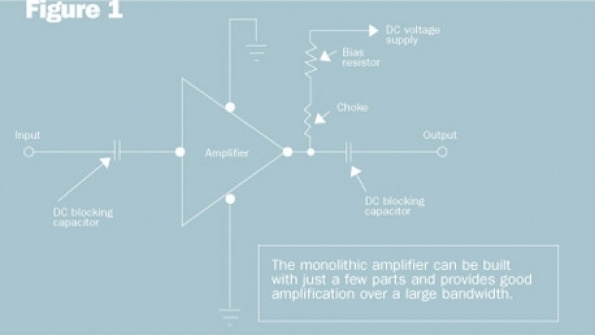
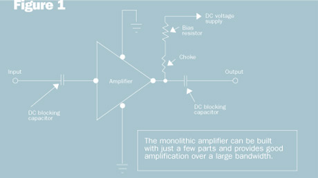
Figure 1 shows a schematic diagram of one such monolithic amplifier. This amplifier uses only five parts, excluding the BNC I/O connectors. A wide range of choices exists for the monolithic amplifier, depending upon the specific need or purpose. Typical specification requirements include supply voltage, necessary gain, bandwidth and flatness, stability, impedance, noise figure, third-order intercept point and output power at the 1 dB compression point. Refer again to Figure 1. The biasing resistor is chosen to produce the specified current in milliamps. The actual value of the biasing resistor depends upon the required bias current and the supply voltage.
Now, let’s talk about some of the important specifications and what they mean.
Gain: This is simply the amplifier’s signal output compared to the signal input — usually stated in decibels.
Bandwidth and flatness: The bandwidth of an amplifier usually is stated in terms of half-power points or points at which the power is diminished by 3 dB. The flatness is usually stated as ±n dB from frequency X to frequency Y. For example, the gain and flatness of an amplifier may be stated as 20 dB, ±1.5 dB, from 20 MHz to 150 MHz.
Stability The stability of an amplifier is a very important specification figure. The stability factor should be listed in the specification sheet as a Rollett K factor. If the K factor is greater than 1, the amplifier is said to be unconditionally stable under all load conditions. If the K factor is less than 1, the amplifier may become very unstable under certain load conditions. We’ll go into greater detail on the K factor later in this article.
Impedance: For communication work in a 50 ohm system, the amplifier should be designed for 50 ohm impedance.
Noise figure: Noise figure is usually stated in decibels. For example, an amplifier noise figure might be stated as 5 dB. If the signal-to-noise ratio at the input to such an amplifier is 30 dB and the noise figure is 5 dB, then the signal-to-noise ratio at the output of the amplifier is 25 dB. The signal-to-noise ratio is degraded by an amount equal to the noise figure of the amplifier.
Third-order intercept point: This specification figure is an indication of how well the amplifier performs under strong signal conditions. This is usually specified in terms of dBm, or decibels referenced to 1 mW. For example, an amplifier’s specification for TOI (third-order intercept) might be listed as +15 dBm. The higher this figure, the better the strong signal performance, but the cost rises accordingly. We’ll examine this in greater detail shortly.
Output power: Output power usually is stated in dBm at the 1 dB compression point. This is the output level at which the amplifier gain is reduced by 1 dB from the small-signal gain. At this point, the amplifier has deviated from the linear I/O relationship and — as the input signal levels are increased beyond this point — distortion products start to rise rapidly. This includes both harmonic and intermodulation distortion products.
S-parameters: The operation of a two-port device, such as an amplifier, can be described by the use of four S-parameters designated as S11, S12, S21 and S22. The subscripts indicate where the signal is measured and where the signal is injected. The input port is designated as port 1, and the output port as port 2. The first subscript indicates the port of measurement. The second subscript indicates the port where the signal is injected.
For S11, the signal is measured at the input, and the signal is injected at the input. This is a measure of the return loss at the input. For S12, the signal is measured at the input and injected at the output. Thus, this is a measure of the isolation of the amplifier between the output and input. For S21, the signal is measured at the output port and injected at the input port. This is a measure of the gain of the amplifier. For S22, the signal is measured and injected at the output port. This is a measure of the return loss at the output port. Much information can be learned about the amplifier by just looking at these S-parameters. The S-parameters are normalized to 1, that is, 1 is 0 dB reference.
S-parameters have magnitude and direction, or angle. The magnitude can be stated in decibels or as a decimal number. All S-parameters except S21 will exhibit a negative decibel figure or a decimal number less than 1. The decimal number will be greater than 1 for S21, which will exhibit a positive decibel figure — assuming the amplifier has gain. It is easy to convert between the decimal and decibel formats. If the figure is given in decibels — such as S21 is 18.4 dB — the equivalent magnitude is equal to:
This means that the voltage at the amplifier output is 8.31 times the signal voltage at the input. Remember, it is important to use the sign of the decibel figure in the formula. Conversely, to convert from a number to decibels, use the formula dB = 20logN. For the example above, the calculation is:
dB = 20log(8.31) = 18.4
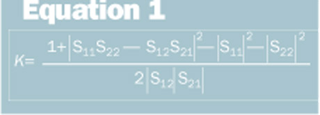
Calculating the stability factor (K): The Rollett stability, or K factor, can be computed from the S-parameters. Equation 1 can be used to calculate the K factor of a specific amplifier to see if it would be unconditionally stable. Table 1 indicates the S-parameter data for such an amplifier operating at 800 MHz.
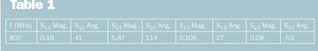
Don’t try this at home unless you have a calculator that can manipulate complex number calculations with ease! Plugging in the values listed in Table 1 yielded a K factor slightly greater than 1.1. Thus, the amplifier should be unconditionally stable for our application. Sometimes, manufacturers actually will list the K factor along with the S-parameters — a great benefit to the user.
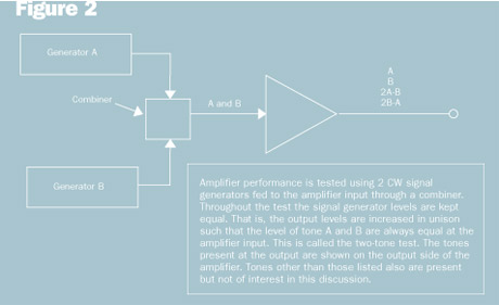
Third-order Intercept: Figure 2 shows an RF amplifier where two signals (A and B) are applied to the input port. As long as the RF amplifier is perfectly linear, the only two signals appearing at the output will be A and B. Of course, no amplifier is perfectly linear, so other mixing products will appear in the output — although they may be at a very low level, assuming low signal levels at the input.
With higher signal levels applied to the input, the distortion products at the output can increase rapidly. To better illustrate the importance of the third-order intercept specification, the graph in Figure 3 shows the third-order intercept point (TOIP) for two amplifiers. Both amplifiers have a gain of 20 dB. The TOIP of one amplifier is +10 dBm, while the other is +30 dBm.
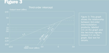
Notice that there are three components to this graph. One represents the linear output-versus-input of the amplifier. This is the line denoted by the 1:1 ratio. This means that the output level (vertical scale) changes decibel for decibel with changes in the input level (horizontal scale). The other two lines, representing the third-order intermod signals, have a 3:1 slope. This means that with a 1 dB change in the level of the two input signals (A and B) the output level of the third-order intermod signal will change by 3 dB. Because of the steep slope of the third-order intermod lines, at some point they will intersect the line representing the desired signals, A and B.
The point of this intersection is called the third-order intercept point. The 20 dB gain of the amplifier is taken into account in the graph. For example, an input level of -40 dBm (horizontal scale) corresponds to an output level of -20 dBm (vertical scale).
Suppose that a receiver has a sensitivity of -110 dBm (0.7 µV). Further suppose that a third-order intermod signal formed by the equation 2A – B falls on the frequency of the desired receive signal. In order to prevent the third-order intermod signal from degrading the reception of a -110 dBm signal, the intermod signal should be suppressed by at least 10 dB below the level of the desired signal. In this case, the level of the third-order intermod signal should be no greater than -120 dBm in order to cause no harm to the desired signal.
In order to determine the maximum input/output level that the two tones can have, a line is drawn from the -120 dBm point on the vertical scale to intersect the third-order intermod slopes. Then, vertical lines are drawn up to the 1:1 slope and down to the horizontal scale. These are shown as dashed lines in Figure 3. The dashed lines intersect the 1:1 slope at the -20 dBm point for the +30 dBm slope and at -33 dBm for the +10 dBm slope
Similarly, the dashed lines intersect the horizontal scale at -40 dBm for the +30 dBm slope and -53 dBm for the +10 dBm slope. Thus, the output level of tones A and B for the +30dBm slope should be no greater than -20 dBm, and the input level to the amplifier should be no greater then -40 dBm.
For the 10 dBm slope, the output level of tones A and B should be no greater than -33 dBm and the input level should be no greater then -53 dBm. If the input/output levels exceed these limits, the third-order intermod signal will exceed the -120 dBm level and will cause degradation to the desired signal at -110 dBm. It is important to note that the third-order intercept point cannot be reached in actual practice because the amplifier would become practically inoperative before this point is reached. However, the TOIP is very useful in understanding how an amplifier will perform with various input levels and in calculating the actual level of a third-order intermod signal at the amplifier output.
When choosing an amplifier, the required specifications for the amplifier would depend upon the particular application. It must provide sufficient gain and it must operate over the required frequency band with stability. If strong signals are anticipated at the input, the amplifier should have a high TOIP. A graph like the one in Figure 3 can help you determine the third-order intermod level at the amplifier output given the input signal levels, A and B. Keep in mind that the graph in Figure 3 assumes that tones A and B are always of equal amplitude. What if tones A and B are not equal? We’ll cover that another time! Until next time — stay tuned!