https://urgentcomm.com/wp-content/themes/ucm_child/assets/images/logo/footer-new-logo.png
  • Home
  • News
  • Multimedia
    • Back
    • Multimedia
    • Video
    • Podcasts
    • Galleries
    • IWCE’s Video Showcase
    • IWCE 2022 Winter Showcase
    • IWCE 2023 Pre-event Guide
  • Commentary
    • Back
    • Commentary
    • Urgent Matters
    • View From The Top
    • All Things IWCE
    • Legal Matters
  • Resources
    • Back
    • Resources
    • Webinars
    • White Papers
    • Reprints & Reuse
  • IWCE
    • Back
    • IWCE
    • Conference
    • Special Events
    • Exhibitor Listings
    • Premier Partners
    • Floor Plan
    • Exhibiting Information
    • Register for IWCE
  • About Us
    • Back
    • About Us
    • Contact Us
    • Advertise
    • Terms of Service
    • Privacy Statement
    • Cookie Policy
  • Related Sites
    • Back
    • American City & County
    • IWCE
    • Light Reading
    • IOT World Today
    • Mission Critical Technologies
    • TU-Auto
  • In the field
    • Back
    • In the field
    • Broadband Push-to-X
    • Internet of Things
    • Project 25
    • Public-Safety Broadband/FirstNet
    • Virtual/Augmented Reality
    • Land Mobile Radio
    • Long Term Evolution (LTE)
    • Applications
    • Drones/Robots
    • IoT/Smart X
    • Software
    • Subscriber Devices
    • Video
  • Call Center/Command
    • Back
    • Call Center/Command
    • Artificial Intelligence
    • NG911
    • Alerting Systems
    • Analytics
    • Dispatch/Call-taking
    • Incident Command/Situational Awareness
    • Tracking, Monitoring & Control
  • Network Tech
    • Back
    • Network Tech
    • Interoperability
    • LMR 100
    • LMR 200
    • Backhaul
    • Deployables
    • Power
    • Tower & Site
    • Wireless Networks
    • Coverage/Interference
    • Security
    • System Design
    • System Installation
    • System Operation
    • Test & Measurement
  • Operations
    • Back
    • Operations
    • Critical Infrastructure
    • Enterprise
    • Federal Government/Military
    • Public Safety
    • State & Local Government
    • Training
  • Regulations
    • Back
    • Regulations
    • Narrowbanding
    • T-Band
    • Rebanding
    • TV White Spaces
    • None
    • Funding
    • Policy
    • Regional Coordination
    • Standards
  • Organizations
    • Back
    • Organizations
    • AASHTO
    • APCO
    • DHS
    • DMR Association
    • ETA
    • EWA
    • FCC
    • IWCE
    • NASEMSO
    • NATE
    • NXDN Forum
    • NENA
    • NIST/PSCR
    • NPSTC
    • NTIA/FirstNet
    • P25 TIG
    • TETRA + CCA
    • UTC
Urgent Communications
  • NEWSLETTER
  • Home
  • News
  • Multimedia
    • Back
    • Video
    • Podcasts
    • Omdia Crit Comms Circle Podcast
    • Galleries
    • IWCE’s Video Showcase
    • IWCE 2023 Pre-event Guide
    • IWCE 2022 Winter Showcase
  • Commentary
    • Back
    • All Things IWCE
    • Urgent Matters
    • View From The Top
    • Legal Matters
  • Resources
    • Back
    • Webinars
    • White Papers
    • Reprints & Reuse
    • UC eZines
    • Sponsored content
  • IWCE
    • Back
    • Conference
    • Why Attend
    • Exhibitor Listing
    • Floor Plan
    • Exhibiting Information
    • Join the Event Mailing List
  • About Us
    • Back
    • About Us
    • Contact Us
    • Advertise
    • Cookie Policy
    • Terms of Service
    • Privacy Statement
  • Related Sites
    • Back
    • American City & County
    • IWCE
    • Light Reading
    • IOT World Today
    • TU-Auto
  • newsletter
  • In the field
    • Back
    • Internet of Things
    • Broadband Push-to-X
    • Project 25
    • Public-Safety Broadband/FirstNet
    • Virtual/Augmented Reality
    • Land Mobile Radio
    • Long Term Evolution (LTE)
    • Applications
    • Drones/Robots
    • IoT/Smart X
    • Software
    • Subscriber Devices
    • Video
  • Call Center/Command
    • Back
    • Artificial Intelligence
    • NG911
    • Alerting Systems
    • Analytics
    • Dispatch/Call-taking
    • Incident Command/Situational Awareness
    • Tracking, Monitoring & Control
  • Network Tech
    • Back
    • Cybersecurity
    • Interoperability
    • LMR 100
    • LMR 200
    • Backhaul
    • Deployables
    • Power
    • Tower & Site
    • Wireless Networks
    • Coverage/Interference
    • Security
    • System Design
    • System Installation
    • System Operation
    • Test & Measurement
  • Operations
    • Back
    • Critical Infrastructure
    • Enterprise
    • Federal Government/Military
    • Public Safety
    • State & Local Government
    • Training
  • Regulations
    • Back
    • Narrowbanding
    • T-Band
    • Rebanding
    • TV White Spaces
    • None
    • Funding
    • Policy
    • Regional Coordination
    • Standards
  • Organizations
    • Back
    • AASHTO
    • APCO
    • DHS
    • DMR Association
    • ETA
    • EWA
    • FCC
    • IWCE
    • NASEMSO
    • NATE
    • NXDN Forum
    • NENA
    • NIST/PSCR
    • NPSTC
    • NTIA/FirstNet
    • P25 TIG
    • TETRA + CCA
    • UTC
acc.com

Tower & Site


Well-grounded principles

Well-grounded principles

Follow these guidelines to eliminate lighting damage
  • Written by Urgent Communications Administrator
  • 1st April 2007

Few disciplines are dominated by as many myths and wives tales as electrical grounding. Everyone agrees that grounding is important to reduce the occurrence of lightning damage but, paradoxically, few sites have good grounds. This article describes some principles of good grounding.

There are three important reasons for proper grounding: ensuring personnel safety, minimizing radio frequency interference and preventing equipment damage from lightning. This article focuses exclusively on the lightning problem. Lightning is an impulse that can create instantaneous down conductor currents greater than 20,000 amperes. Because it is an impulse, a lightning surge produces alternating current with frequency content as high as 100 MHz.

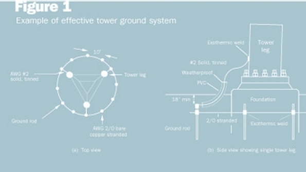
A good ground is a low-impedance bond to an effective earth electrode system, which is a network of buried conductors around the tower designed to create a low resistance-to-earth. Tower earth electrode systems typically consist of a set of driven ground rods configured in a ring around the tower, with the rods bonded together by a large copper conductor (AWG size 1/0 or larger). Each leg of the tower should be bonded to the earth-electrode system using an exothermic weld. A typical tower ground system is shown in Figure 1.

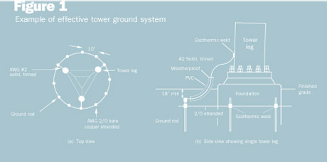
Ground rods should be driven below the frost line, and all buried connections must be exothermic welded. In soils with poor conductivity, it may be necessary to use chemically treated rods rather than conventional copper-clad steel rods. The PVC pipe in Figure 1 insulates the surface soil from the lightning surge current, thereby reducing the step potential, a personnel safety hazard. (It generally is not a good idea to stand near an antenna tower during a thunderstorm.)

The simplest and most common earth electrode system is a single ground rod, usually driven by the electrician when the electrical service is installed. From Military Handbook 419, we can determine the resistance-to-earth of a single ground rod by using Equation 1 [2].

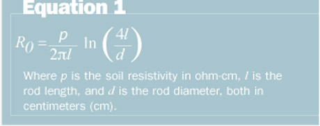
For example, if the soil resistivity is 50,000 ohm-cm, the rod diameter is 2 cm (¾ inches), and the rod length is 305 cm (10 feet), the resistance-to-earth is 167 ohms. Typically, one wants a resistance-to-earth less than 10 ohms, so some improvement is needed.

Improvements come in several forms. One can lengthen the rod, increase the diameter of the rod, add more rods, bond to structural steel or other buried metal, or use chemical rods. Chemical rods increase the conductivity of the soil around the rod, increasing its effective diameter.

Real-world grounding systems often are quite complex when dealing with non-homogeneous soil conditions. Measurements are required to verify resistance-to-earth. Unfortunately, one cannot measure resistance-to-earth with a common multimeter. Specialized equipment and techniques are required. The preferred technique is the fall-of-potential method, illustrated in Figure 2.

The resistance-to-earth of the electrode under test is simply V/I, where V is the voltage reading at the voltmeter and I is the current reading at the ammeter. The voltage source is usually AC, operating at a frequency that is not a harmonic of 60 Hz.

The correct reading is found when distance P is 62% of C [2]. It also is important that C be large relative to the largest dimension — the diagonal — of the earth-electrode system. A good rule of thumb is that the ratio of C to the system diameter should be at least 9 to 1.

Equally important as the earth electrode system is the down conductor bonded to it. Lightning creates alternating current in down conductors, so we are interested in the properties of down conductors at high frequencies. We recall that impedance, Z, consists of two parts, as shown in Equation 2.

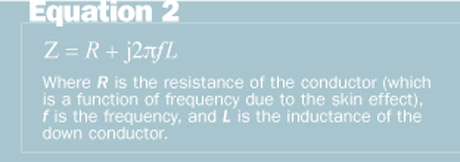
We know that coils of wire have high inductance, but even a straight wire has some inductance. For example, a straight, 30-foot-long, No. 2 copper wire has an impedance of 9050 ohms — at ƒ=100 MHz — almost entirely due to inductance. To reduce inductance, we should avoid sharp bends, but we also can reduce inductance by creating more surface area. For example, a 3-inch-wide copper strap of the same length has an impedance of only 6900 ohms. Strap generally is a better down conductor than wire, but mechanical considerations often dictate that round conductors be used.

Let’s wrap up with some common grounding mistakes:

Installing down conductors from high on the tower: Installers are sometimes told they must install a copper down conductor from the antenna to the earth electrode system. The author has seen more than 200 feet of AWG No. 2 wire installed on a tower to meet this misguided requirement. True, copper has better conductivity than galvanized steel, but the impedance of the tower is much lower than No. 2 copper wire for two reasons: the larger surface area of tower members creates lower inductance and the multiple current paths to the ground create lower overall impedance.

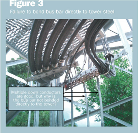
Figure 3 depicts a similar mistake. Here, the installer mounted a bus bar about 10 feet above grade near the base of the tower. He bonded three down conductors to the bus bar, which is good, but he failed to bond the bus bar to a tower member. The large surface area and multiple paths created by tower members create a lower impedance path to ground than the three small down conductors. The concern here is that a lightning surge might find the coaxial cable to be a lower impedance path to ground (through the radio cabinet) than the three down conductors. A mitigating circumstance is that the bend in the coaxial cable creates higher impedance, making it somewhat less attractive to the lightning surge.

Failure to bond building structural steel to an earth electrode system: Copper and steel conductors embedded in concrete also create an effective ground. Such a ground system is called a Ufer ground (after its inventor, Herbert Ufer, who was a consultant to the U.S. Army during World War II). Too often, the designer fails to bring conductors outside the foundation for bonding to the earth electrode system.

When structural steel is bonded to the earth electrode system, the results can be quite dramatic. The author participated in one mountain-top project where the measured resistance-to-earth of a 20-rod, building earth electrode system — prior to bonding to foundation steel — was 150 ohms. After bonding foundation steel to the earth electrode system (all below grade), the resistance-to-earth was 1.0 ohm.

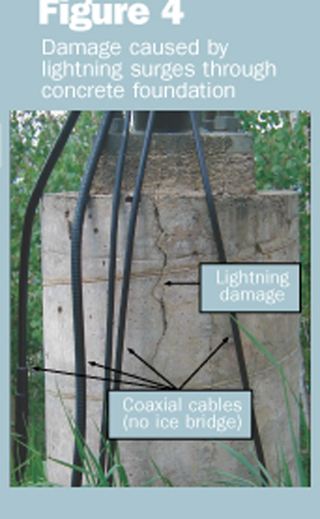
A word of caution: A Ufer ground consisting solely of the tower foundation is a bad idea. Lightning surges passing through the foundation can vaporize water in the concrete and damage the foundation through rapid expansion of steam. An example of this unfortunate event is shown in Figure 4. This particular tower had no earth electrode system, other than the leg foundations.

Failure to prevent conduit from acting as an RF choke: It is common for building codes to require that in-building, insulated (green wire) ground conductors be routed inside to the building ground through steel conduit. Unless the wire is electrically bonded to the conduit when it enters and leaves it, the steel conduit acts as an RF choke, presenting high impedance to alternating current, including lightning surges.

Space does not permit us to cover all the best practices for grounding, so the author recommends the industry and government guides listed below.


Jay Jacobsmeyer is president of Pericle Communications Co., a consulting engineering firm located in Colorado Springs, Colo. He holds bachelor’s and master’s degrees in Electrical Engineering from Virginia Tech and Cornell University, respectively, and has more than 25 years experience as a radio frequency engineer.

References:

  1. Motorola R-56, “Standards and Guidelines for Communications Sites,” 2000.

  2. MIL-HDBK 419, “Grounding, Bonding and Shielding for Electronic Equipment and Facilities,” 1987.

Tags: Tower & Site

Most Recent


  • Crown Castle's fiber and small cell business under fire – again
    Elliott Investment Management, an activist investor firm, is taking aim at Crown Castle again, arguing the company needs to overhaul its management and potentially put its fiber business up for sale. Importantly, Elliott said it now owns roughly $2 billion in Crown Castle stock. That’s double what the company owned in 2020 when it embarked on […]
  • Cellular's satellite backhaul options abound with no clear winner
    Wireless network engineers who are looking for more ways to keep their cell sites connected need only to cast their eyes skyward. There, in space, is a growing range of options for cell site satellite backhaul. SpaceX’s Starlink, Eutelsat OneWeb, Amazon’s Project Kuiper, Telesat’s Lightspeed and Rivada Space Networks are some of the new names […]
  • Check out key takeaways from Disaster Management Symposium webinars, register to view archives
    The inaugural Disaster Management Symposium was conducted Nov. 8, when consecutive hour-long webinars featured expert panelists exploring various aspects of the three main phases of a disaster for public safety and governments: planning, response and recovery. This virtual symposium was a joint effort of IWCE’s Urgent Communications, IWCE and American City & County. If you […]
  • 6G Summit brings unusual plea from carriers: Slow your roll
    NEW YORK – BROOKLYN 6G SUMMIT – On the first day of a conference meant to serve up 6G’s possibilities, cold water followed a coffee break.  “We’re getting a little bit worn out with the economics of the industry,” AT&T technology EVP Chris Sambar said in a keynote last week at the Brooklyn 6G Summit. […]

Leave a comment Cancel reply

To leave a comment login with your Urgent Comms account:

Log in with your Urgent Comms account

Or alternatively provide your name, email address below:

Your email address will not be published. Required fields are marked *

Related Content

  • U.S. telecom groups warn of network construction delays from chip shortages
  • Rakuten says chips crunch 'much worse' than expected
  • LA-RICS hopes P25 network will be ready in 2023, executive director says
  • Private wireless networks in the US start going public

Commentary


Land mobile radio (LMR) systems are just as vulnerable to cyberattacks as any other networks used in the public-safety sector. Here’s what to do about it.

  • 1
7th November 2023

September 3GPP Plenary meetings feature Release 18 progress, Release 19 beginnings

13th October 2023

Better technology can help solve the public-safety staffing crisis

26th June 2023
view all

Events


UC Ezines


IWCE 2019 Wrap Up

13th May 2019
view all

Twitter


Newsletter

Sign up for UrgentComm’s newsletters to receive regular news and information updates about Communications and Technology.

Expert Commentary

Learn from experts about the latest technology in automation, machine-learning, big data and cybersecurity.

Business Media

Find the latest videos and media from the market leaders.

Media Kit and Advertising

Want to reach our digital and print audiences? Learn more here.

DISCOVER MORE FROM INFORMA TECH

  • American City & County
  • IWCE
  • Light Reading
  • IOT World Today
  • Mission Critical Technologies
  • TU-Auto

WORKING WITH US

  • About Us
  • Contact Us
  • Events
  • Careers

FOLLOW Urgent Comms ON SOCIAL

  • Privacy
  • CCPA: “Do Not Sell My Data”
  • Cookie Policy
  • Terms
Copyright © 2023 Informa PLC. Informa PLC is registered in England and Wales with company number 8860726 whose registered and Head office is 5 Howick Place, London, SW1P 1WG.