Not your father’s radio network
Modern land mobile radio systems are packet-switched networks that contrast sharply with legacy systems using circuit-switched connections. The circuit switch operates like the original telephone network, where each call requires a physical connection between two end users that is maintained until the call is complete. The circuit switch manages some number of narrowband channels, and each channel is dedicated to a single conversation for the duration of the call. A trunked radio network is an example of a circuit-switched network.
In contrast, the packet switch manages a single broadband channel by time-sharing the channel on a packet-by-packet basis. Access is controlled using a multiple access method such as carrier sense multiple access with collision avoidance (CSMA/CA). Computer professionals often call the broadband channel the medium, and methods for controlling the medium fall into a class of protocols called medium access control (MAC).
In packet networks, a single message or conversation is divided into many packets that typically are interleaved in time with packets from other users. Packets from the same conversation can arrive at different times and even out of order. The uncertain delivery time makes packet-switched networks less suitable for voice traffic, but special protocols used by voice-over-IP (VoIP) systems prioritize voice packets so they are assembled more quickly and cause no noticeable delays to the user. IEEE 802.11 (Wi-Fi) networks are packet-switched networks.
Circuit switching is inefficient for bursty traffic, but push-to-talk voice calls — and all data calls — are inherently bursty. Furthermore, practically all computer networks are packet-switched. Eventually, the convergence of computer and radio technology will draw all radio traffic into packet-switched networks. This article examines the protocols used on packet-switched radio networks and the methods for managing bandwidth on these networks.
The OSI model
Most computer networks follow the reference model for open systems interconnection (OSI) as published by the International Standards Organization (ISO). The OSI model has seven layers that communicate between end systems. The user generates a message at the top layer called the application layer (layer 7), and the message moves down the protocol stack to the physical layer (layer 1), where the message is physically transmitted over the communications medium (cable or radio). At the distant end, the message moves up the stack until it reaches the corresponding application layer.
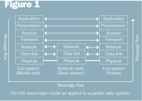
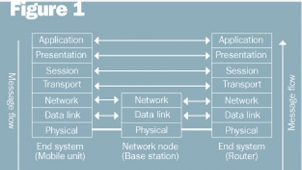
Intermediate nodes in an OSI network require only the bottom layer functions of the OSI model. For example, if our network is a packet radio system, the network node or base station needs to implement only the physical, data link and network layers. Such a configuration is shown in Figure 1. Note that we are using the normal convention of arrows between equivalent layers. These arrows indicate a virtual connection except at the physical layer, where there is an actual connection. Messages must travel down the stack and across the channel at the physical layer.

Computer networks almost universally operate under a somewhat different model called the TCP/IP model. Unlike the OSI model, the TCP/IP model is not an international standard, and its definitions are somewhat different. The TCP/IP model has five layers, with the first four layers identical to the OSI model. The fifth layer, called application, combines the session, presentation and application layers of the OSI model.
When computer professionals speak of bandwidth management, they mean management of a medium characterized by some gross bit rate, whether it originates from a radio network or a landline network. When radio professionals speak of bandwidth management, they usually mean spectrum management, which is the efficient use of allocated radio spectrum shared by multiple users.
Bandwidth management (computers)
Information technology (IT) professionals are familiar with the many tools and techniques for managing network bandwidth. However, a good reference resource for obtaining more details on bandwidth management in computer networks is How to Accelerate Your Internet, edited by Rob Flickenger, which is available for free from http://bwmo.net.
Spectrum management (radios)
The goal of spectrum management is to maximize users per MHz per square kilometer while maintaining some minimum service threshold. The service threshold may have multiple parts that apply simultaneously, such as minimum signal strength, maximum probability of call blocking, minimum subjective voice quality (e.g., DAQ = 3.4) and minimum throughput.
To illustrate good spectrum management in a packet radio network, let’s use 802.11b as an example. Assume that the service area cannot be covered by a single access point (AP) because one AP cannot provide adequate radio coverage or support the expected number of simultaneous users. Given these assumptions, we face two constraints:
- Spatially adjacent co-channel APs will create dead zones between cells where service will be unsatisfactory unless the network is lightly loaded.
- Only three non-overlapping 802.11 channels exist in the 2.4 GHz band: Channel 1 at 2412 MHz, Channel 6 at 2437 MHz and Channel 11 at 2462 MHz.
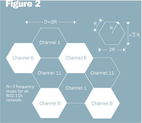
One way to address these constraints is to borrow a concept from cellular phone networks and use an N=3 frequency reuse pattern, which is illustrated in Figure 2. With N=3 reuse, each co-channel cell is separated by three cell radii, which create enough additional path loss that co-channel interference is minimized. Because a single AP can handle only a finite number of simultaneous users (e.g., 100) and a finite amount of traffic, such a network also maximizes the number of users per square kilometer.

One principle of traffic engineering applies to both circuit-switched and packet-switched networks: All users should share one set of channels (circuit-switched) or one medium (packet-switched) for the most efficient use of the available bandwidth. IEEE 802.11 networks are no exception. A network coordination function minimizes collisions between users on the same network, but harmful interference and low throughput result when two separate networks operate in the same area on the same frequencies.
Another example is 4.9 GHz networks. In the 4.9 GHz band, the FCC authorizes channel bandwidths of 1, 5, 10 and 20 MHz. Existing IEEE 802.11 standards specify channel bandwidths of 10 and 20 MHz, but some vendors also offer 5 MHz channels. The most common channel bandwidth used at 4.9 GHz is 20 MHz because it allows the use of the 802.11a protocol and offers the highest maximum bit rate of 54 Mb/s.
Unfortunately, there is only 50 MHz authorized in the 4.9 GHz band, so there are only two and one half 20 MHz channels. This limitation creates a problem if each agency in a metropolitan area wants its own radio channel — there simply aren’t enough channels. A better approach is to operate one metropolitan-wide network using 10 MHz channels. The 10 MHz channel will allow an N=3 reuse pattern with two channels left over for contingencies or the occasional point-to-point link. The 10 MHz channel results in a 3 dB improvement in sensitivity compared with the 20 MHz channel, and it is more robust in the presence of multipath-induced delay spread. The only drawback to the 10 MHz channel is that the maximum bit rate is cut in half.
Jay Jacobsmeyer is president of Pericle Communications Co., a consulting engineering firm in Colorado Springs, Colo. He holds BS and MS degrees in electrical engineering from Virginia Tech and Cornell University, respectively, and has more than 25 years of experience as a radio frequency engineer.


