https://urgentcomm.com/wp-content/themes/ucm_child/assets/images/logo/footer-new-logo.png
  • Home
  • News
  • Multimedia
    • Back
    • Multimedia
    • Video
    • Podcasts
    • Galleries
    • IWCE’s Video Showcase
    • IWCE 2022 Winter Showcase
    • IWCE 2023 Pre-event Guide
  • Commentary
    • Back
    • Commentary
    • Urgent Matters
    • View From The Top
    • All Things IWCE
    • Legal Matters
  • Resources
    • Back
    • Resources
    • Webinars
    • White Papers
    • Reprints & Reuse
  • IWCE
    • Back
    • IWCE
    • Conference
    • Special Events
    • Exhibitor Listings
    • Premier Partners
    • Floor Plan
    • Exhibiting Information
    • Register for IWCE
  • About Us
    • Back
    • About Us
    • Contact Us
    • Advertise
    • Terms of Service
    • Privacy Statement
    • Cookie Policy
  • Related Sites
    • Back
    • American City & County
    • IWCE
    • Light Reading
    • IOT World Today
    • Mission Critical Technologies
    • TU-Auto
  • In the field
    • Back
    • In the field
    • Broadband Push-to-X
    • Internet of Things
    • Project 25
    • Public-Safety Broadband/FirstNet
    • Virtual/Augmented Reality
    • Land Mobile Radio
    • Long Term Evolution (LTE)
    • Applications
    • Drones/Robots
    • IoT/Smart X
    • Software
    • Subscriber Devices
    • Video
  • Call Center/Command
    • Back
    • Call Center/Command
    • Artificial Intelligence
    • NG911
    • Alerting Systems
    • Analytics
    • Dispatch/Call-taking
    • Incident Command/Situational Awareness
    • Tracking, Monitoring & Control
  • Network Tech
    • Back
    • Network Tech
    • Interoperability
    • LMR 100
    • LMR 200
    • Backhaul
    • Deployables
    • Power
    • Tower & Site
    • Wireless Networks
    • Coverage/Interference
    • Security
    • System Design
    • System Installation
    • System Operation
    • Test & Measurement
  • Operations
    • Back
    • Operations
    • Critical Infrastructure
    • Enterprise
    • Federal Government/Military
    • Public Safety
    • State & Local Government
    • Training
  • Regulations
    • Back
    • Regulations
    • Narrowbanding
    • T-Band
    • Rebanding
    • TV White Spaces
    • None
    • Funding
    • Policy
    • Regional Coordination
    • Standards
  • Organizations
    • Back
    • Organizations
    • AASHTO
    • APCO
    • DHS
    • DMR Association
    • ETA
    • EWA
    • FCC
    • IWCE
    • NASEMSO
    • NATE
    • NXDN Forum
    • NENA
    • NIST/PSCR
    • NPSTC
    • NTIA/FirstNet
    • P25 TIG
    • TETRA + CCA
    • UTC
Urgent Communications
  • NEWSLETTER
  • Home
  • News
  • Multimedia
    • Back
    • Video
    • Podcasts
    • Omdia Crit Comms Circle Podcast
    • Galleries
    • IWCE’s Video Showcase
    • IWCE 2023 Pre-event Guide
    • IWCE 2022 Winter Showcase
  • Commentary
    • Back
    • All Things IWCE
    • Urgent Matters
    • View From The Top
    • Legal Matters
  • Resources
    • Back
    • Webinars
    • White Papers
    • Reprints & Reuse
    • UC eZines
    • Sponsored content
  • IWCE
    • Back
    • Conference
    • Why Attend
    • Exhibitor Listing
    • Floor Plan
    • Exhibiting Information
    • Join the Event Mailing List
  • About Us
    • Back
    • About Us
    • Contact Us
    • Advertise
    • Cookie Policy
    • Terms of Service
    • Privacy Statement
  • Related Sites
    • Back
    • American City & County
    • IWCE
    • Light Reading
    • IOT World Today
    • TU-Auto
  • newsletter
  • In the field
    • Back
    • Internet of Things
    • Broadband Push-to-X
    • Project 25
    • Public-Safety Broadband/FirstNet
    • Virtual/Augmented Reality
    • Land Mobile Radio
    • Long Term Evolution (LTE)
    • Applications
    • Drones/Robots
    • IoT/Smart X
    • Software
    • Subscriber Devices
    • Video
  • Call Center/Command
    • Back
    • Artificial Intelligence
    • NG911
    • Alerting Systems
    • Analytics
    • Dispatch/Call-taking
    • Incident Command/Situational Awareness
    • Tracking, Monitoring & Control
  • Network Tech
    • Back
    • Cybersecurity
    • Interoperability
    • LMR 100
    • LMR 200
    • Backhaul
    • Deployables
    • Power
    • Tower & Site
    • Wireless Networks
    • Coverage/Interference
    • Security
    • System Design
    • System Installation
    • System Operation
    • Test & Measurement
  • Operations
    • Back
    • Critical Infrastructure
    • Enterprise
    • Federal Government/Military
    • Public Safety
    • State & Local Government
    • Training
  • Regulations
    • Back
    • Narrowbanding
    • T-Band
    • Rebanding
    • TV White Spaces
    • None
    • Funding
    • Policy
    • Regional Coordination
    • Standards
  • Organizations
    • Back
    • AASHTO
    • APCO
    • DHS
    • DMR Association
    • ETA
    • EWA
    • FCC
    • IWCE
    • NASEMSO
    • NATE
    • NXDN Forum
    • NENA
    • NIST/PSCR
    • NPSTC
    • NTIA/FirstNet
    • P25 TIG
    • TETRA + CCA
    • UTC
acc.com

Test & Measurement


Using directional couplers

Using directional couplers

Understanding how they work is the key to getting the most out of them
  • Written by Urgent Communications Administrator
  • 1st June 2008

Many RF test and measurement applications require the use of directional couplers, whether standalone or as an integral part of test instruments such as directional wattmeters. Typically, a directional coupler is a four-port device; the ports might be labeled input, output, forward and reverse. A four-port coupler also is called a bidirectional coupler. Important specifications for directional couplers are main line insertion loss, frequency range, coupling factor, directivity, coupling flatness and maximum power input.

The main line loss is the insertion loss between the input and output ports. If a 50-ohm termination were connected to both the forward (FOR) and reverse (REV) ports, the main line loss would be the same in either direction — from input to output or from output to input. If a 50-ohm termination were connected to only one of the coupled ports, either FOR or REV, the main line loss no longer would be the same in either direction. However, for higher coupling factors, say 20-30 dB or so, the difference between the losses in opposite directions is negligible in practical applications. The coupled port that is terminated with a 50-ohm impedance becomes the isolated port. In a three-port directional coupler (as opposed to a bidirectional coupler) the fourth port is not made available externally but is terminated internally in a 50-ohm resistor. An internal termination generally provides a better impedance match and results in a better directivity figure.

The theoretical minimum insertion loss depends on the degree of coupling between the main line and the coupled port(s). Higher coupling factors will cause less insertion loss in the main line. For example, a coupling factor of 30 dB will cause less insertion loss than a coupling factor of 20 dB. The formula for determining the minimum main line insertion loss is:

IL=10 log(1-10(-C/10))

For 20 dB coupling and substituting 20 for C in the formula yields a figure of 0.044 dB. For 30 dB coupling the figure is 0.0043 dB. Coupling affects the main line insertion loss from input to output because any signal appearing at the coupled port(s) is taken from the signal at the input on the main line.

The coupling factor determines the level of the signal attenuation between input and the coupled port associated with the input, or between the output and the coupled port associated with the output.

Referring to Figure 1 and assuming a coupling factor of 20 dB, if a signal at a level of 0 dBm is applied to the input, the level appearing at the FOR coupled port will be -20 dBm. If the connections to the signal generator and the RF voltmeter were reversed, the RF voltmeter would still indicate -20 dBm; that is, the coupling between the input and forward ports is bidirectional. The output and reverse ports are terminated in 50 ohms. It is always a good practice to terminate unused ports in 50 ohms (assuming a 50-ohm system). Referring again to Figure 1, the signal generator could be connected to the output port and the RF voltmeter to the reverse port and the results would be the same. Again, unused ports are terminated in 50 ohms.

Directivity is one of the most important characteristics or specifications of directional couplers. Directivity can best be defined by an example. The setup in Figure 2 is the same as Figure 1, except the RF voltmeter is now connected to the reverse port and the forward port is terminated in 50 ohms. The RF voltmeter now indicates much less than -20 dBm. The signal level at the reverse port will be equal to the input signal level minus the coupling factor minus the directivity. If the coupling factor is 20 dB and directivity is 30 dB, the signal level at the reverse port will be equal to the input signal level (0 dBm) minus 50 dB, or -50 dBm. This assumes a perfect 50-ohm match at the output port. If the output port were left open (unterminated), the RF voltmeter would indicate -20 dBm because the signal power is completely reflected back into the output port and coupled (with a 20dB loss) to the reverse port.

It is easy to see why directivity is such an important characteristic if the directional coupler is to be used to compare forward and reflected power, as it is in a directional wattmeter. To better understand how coupler directivity affects the accuracy of a wattmeter, refer to Figure 3. The graph is based on a directional coupler having a directivity of 25 dB with a forward power of 100 W at the input and a reflected power of 10 W at the output.

A portion of the signal power from the reverse signal is mixed with the forward signal power and vice versa. In a directional wattmeter, these “contaminant” signals cause errors in the measurement of forward and reflected power. Normally, the forward power reading is not significantly affected by the contaminant because the forward power is usually much higher than the reflected power. However, the reflected power reading can be seriously affected by the contaminant from the forward signal. This is especially true at relatively low reflected power levels.

To determine the effect of these contaminants, the power levels are converted to voltage levels (in 50 ohms) and then analyzed using phasors. Figure 4 shows the various voltages and the resultants. The voltage at A represents the voltage in the 100 W forward signal. The voltage at E represents the voltage in the 10 W reflected signal. The voltage in the contaminant signal that is 25 dB down from the reflected voltage (E) is shown at B. At one point, the phasors representing the desired and contaminant signals will be in phase and will add directly. This is shown at C. At another point, the phasors will be 180° out of phase and will subtract directly. This is shown at D. At other phase relationships, the voltages will be combined vectorially and will fall between these two extremes. Similarly, a contaminant from the forward signal is shown at F and is 25 dB down from A. The sum and difference of E and F produces the resultants G and H.

As mentioned earlier, some directional couplers provide only three ports. In this case, the third port is simply labeled the “coupled” port instead of forward or reverse. The fourth port is terminated internally with a near-perfectly matched 50-ohm resistor. In this case, the fourth port is not available externally and therefore is not really considered a port, as such.

The obvious disadvantage of this arrangement is that a sample of both the forward and reflected signals is not available simultaneously. Connections have to be switched to measure one and then the other. Directivity measurement requires a comparison of the signal level at the coupled port with the signal generator and load connected to the input and output ports respectively, and then with the generator and load connections reversed.

Dual-directional couplers can be fashioned by connecting two three-port couplers back to back. The two output ports are connected together. This provides two coupled ports that can be used for simultaneous monitoring of the forward and reflected signals. The two remaining ports are both labeled “input,” but either can be used as input or output.

Coupling flatness is sometimes referred to as frequency sensitivity. It is a measure of how much the level at the coupled port changes over a specified frequency range with the signal level at the input port held constant. An example might be ±0.5 dB from 5 to 300 MHz.

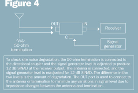
Figure 4 shows a typical use for a three-port directional coupler. Directional couplers can be used for a variety of test-and-measurement procedures. As a rule of thumb, when using a directional coupler to measure voltage standing wave ratio (VSWR), the directivity of the coupler should be at least 20 dB greater than the return loss (VSWR) to be measured. For example, if the return loss to be measured is 20 dB, the directivity of the coupler should be no less than 40 dB. When this is the case, the measurement error will be no greater than 1 dB.

Understanding how directional couplers operate is the key to getting maximum benefit from their use. The material presented here should serve as a primer on the use of directional couplers. However, much can be learned by hands-on experimentation with a directional coupler. Some directional couplers are designed for high-power applications — others are not. Just remember, don’t apply power in excess of the manufacturer’s rating — otherwise, you’ll let the smoke out!

Until next time — stay tuned!

Tags: Test & Measurement

Most Recent


  • Ransomware's favorite target: Critical infrastructure and its industrial control systems
    National defense and security experts long predicted that future warfare would not be waged by firearms but with code designed to disable services people depend on for daily life. In May 2021, security experts’ worst fears came true, when a ransomware attack struck the Colonial Pipeline. Gas delivery to most of the US Northeast halted almost […]
  • Most satellite D2D services will fail, predicts Iridium CTO
    Most direct-to-device (D2D) satellite companies now hitting the market are likely to fail, Iridium CTO Greg Felton has warned. Speaking in an online forum Tuesday, he said the new players are yet to test out their business models. “Right now there’s a lot of investment and a lot of different ideas being tried out and most […]
  • Report: Technology can aid wildfire response that’s ‘stuck in the last century’
    With each passing season, the growing threat of wildfire and its impact on life safety, property, and the economy is underscored by dramatic fire events that ecologically alter entire regions, uproot communities and cost taxpayers billions of dollars. Last year, 68,988 wildfires burned 7.6 million acres of American land. And as of the end of […]
  • What happened in that cyberattack? With some cloud services, you may never know
    Major cloud platforms, such as Google Cloud Platform (GCP), fail to adequately log the event data that could facilitate the detection of compromises and the forensic analysis during post-compromise response, according to an analysis. Cloud security firm Mitiga stated in an advisory published on March 1 that the Google Cloud Platform allows customers to turn […]

Leave a comment Cancel reply

To leave a comment login with your Urgent Comms account:

Log in with your Urgent Comms account

Or alternatively provide your name, email address below:

Your email address will not be published. Required fields are marked *

Related Content

  • New Orleans-area 911 center inks multiyear APEX deal with Carbyne to replace call-handling system
  • Cyber is the new Cold War, and AI is the arms race
  • Microsoft patches 6 zero-day vulnerabilities under active attack
  • AI energizes remote monitoring of patients, fuels bidirectional health care

Commentary


Updated: How ‘sidelink’ peer-to-peer communications can enhance public-safety operations

  • 1
27th February 2023

NG911 needed to secure our communities and nation

24th February 2023

How 5G is making cities safer, smarter, and more efficient

26th January 2023
view all

Events


UC Ezines


IWCE 2019 Wrap Up

13th May 2019
view all

Twitter


UrgentComm

Microsoft Outlook vulnerability could be 2023’s ‘It’ bug dlvr.it/SlC3Hh

20th March 2023
UrgentComm

Getting to know the how–and why–of the telecom cloud dlvr.it/SlBbD1

20th March 2023
UrgentComm

Zipline delivery drone docks, charges by itself dlvr.it/SlBNWy

20th March 2023
UrgentComm

State and local leaders can alleviate the burden on public-safety personnel by tackling three workforce trends dlvr.it/SlBH89

20th March 2023
UrgentComm

6G is shaping up to disappoint, and the industry can blame itself dlvr.it/Sl918J

20th March 2023
UrgentComm

Change is coming to the network detection and response (NDR) market dlvr.it/Sl4cts

18th March 2023

Newsletter

Sign up for UrgentComm’s newsletters to receive regular news and information updates about Communications and Technology.

Expert Commentary

Learn from experts about the latest technology in automation, machine-learning, big data and cybersecurity.

Business Media

Find the latest videos and media from the market leaders.

Media Kit and Advertising

Want to reach our digital and print audiences? Learn more here.

DISCOVER MORE FROM INFORMA TECH

  • American City & County
  • IWCE
  • Light Reading
  • IOT World Today
  • Mission Critical Technologies
  • TU-Auto

WORKING WITH US

  • About Us
  • Contact Us
  • Events
  • Careers

FOLLOW Urgent Comms ON SOCIAL

  • Privacy
  • CCPA: “Do Not Sell My Data”
  • Cookie Policy
  • Terms
Copyright © 2023 Informa PLC. Informa PLC is registered in England and Wales with company number 8860726 whose registered and Head office is 5 Howick Place, London, SW1P 1WG.