https://urgentcomm.com/wp-content/themes/ucm_child/assets/images/logo/footer-new-logo.png
  • Home
  • News
  • Multimedia
    • Back
    • Multimedia
    • Video
    • Podcasts
    • Galleries
    • IWCE’s Video Showcase
    • IWCE 2022 Winter Showcase
    • IWCE 2023 Pre-event Guide
  • Commentary
    • Back
    • Commentary
    • Urgent Matters
    • View From The Top
    • All Things IWCE
    • Legal Matters
  • Resources
    • Back
    • Resources
    • Webinars
    • White Papers
    • Reprints & Reuse
  • IWCE
    • Back
    • IWCE
    • Conference
    • Special Events
    • Exhibitor Listings
    • Premier Partners
    • Floor Plan
    • Exhibiting Information
    • Register for IWCE
  • About Us
    • Back
    • About Us
    • Contact Us
    • Advertise
    • Terms of Service
    • Privacy Statement
    • Cookie Policy
  • Related Sites
    • Back
    • American City & County
    • IWCE
    • Light Reading
    • IOT World Today
    • Mission Critical Technologies
    • TU-Auto
  • In the field
    • Back
    • In the field
    • Broadband Push-to-X
    • Internet of Things
    • Project 25
    • Public-Safety Broadband/FirstNet
    • Virtual/Augmented Reality
    • Land Mobile Radio
    • Long Term Evolution (LTE)
    • Applications
    • Drones/Robots
    • IoT/Smart X
    • Software
    • Subscriber Devices
    • Video
  • Call Center/Command
    • Back
    • Call Center/Command
    • Artificial Intelligence
    • NG911
    • Alerting Systems
    • Analytics
    • Dispatch/Call-taking
    • Incident Command/Situational Awareness
    • Tracking, Monitoring & Control
  • Network Tech
    • Back
    • Network Tech
    • Interoperability
    • LMR 100
    • LMR 200
    • Backhaul
    • Deployables
    • Power
    • Tower & Site
    • Wireless Networks
    • Coverage/Interference
    • Security
    • System Design
    • System Installation
    • System Operation
    • Test & Measurement
  • Operations
    • Back
    • Operations
    • Critical Infrastructure
    • Enterprise
    • Federal Government/Military
    • Public Safety
    • State & Local Government
    • Training
  • Regulations
    • Back
    • Regulations
    • Narrowbanding
    • T-Band
    • Rebanding
    • TV White Spaces
    • None
    • Funding
    • Policy
    • Regional Coordination
    • Standards
  • Organizations
    • Back
    • Organizations
    • AASHTO
    • APCO
    • DHS
    • DMR Association
    • ETA
    • EWA
    • FCC
    • IWCE
    • NASEMSO
    • NATE
    • NXDN Forum
    • NENA
    • NIST/PSCR
    • NPSTC
    • NTIA/FirstNet
    • P25 TIG
    • TETRA + CCA
    • UTC
Urgent Communications
  • NEWSLETTER
  • Home
  • News
  • Multimedia
    • Back
    • Video
    • Podcasts
    • Omdia Crit Comms Circle Podcast
    • Galleries
    • IWCE’s Video Showcase
    • IWCE 2023 Pre-event Guide
    • IWCE 2022 Winter Showcase
  • Commentary
    • Back
    • All Things IWCE
    • Urgent Matters
    • View From The Top
    • Legal Matters
  • Resources
    • Back
    • Webinars
    • White Papers
    • Reprints & Reuse
    • UC eZines
    • Sponsored content
  • IWCE
    • Back
    • Conference
    • Why Attend
    • Exhibitor Listing
    • Floor Plan
    • Exhibiting Information
    • Join the Event Mailing List
  • About Us
    • Back
    • About Us
    • Contact Us
    • Advertise
    • Cookie Policy
    • Terms of Service
    • Privacy Statement
  • Related Sites
    • Back
    • American City & County
    • IWCE
    • Light Reading
    • IOT World Today
    • TU-Auto
  • newsletter
  • In the field
    • Back
    • Internet of Things
    • Broadband Push-to-X
    • Project 25
    • Public-Safety Broadband/FirstNet
    • Virtual/Augmented Reality
    • Land Mobile Radio
    • Long Term Evolution (LTE)
    • Applications
    • Drones/Robots
    • IoT/Smart X
    • Software
    • Subscriber Devices
    • Video
  • Call Center/Command
    • Back
    • Artificial Intelligence
    • NG911
    • Alerting Systems
    • Analytics
    • Dispatch/Call-taking
    • Incident Command/Situational Awareness
    • Tracking, Monitoring & Control
  • Network Tech
    • Back
    • Cybersecurity
    • Interoperability
    • LMR 100
    • LMR 200
    • Backhaul
    • Deployables
    • Power
    • Tower & Site
    • Wireless Networks
    • Coverage/Interference
    • Security
    • System Design
    • System Installation
    • System Operation
    • Test & Measurement
  • Operations
    • Back
    • Critical Infrastructure
    • Enterprise
    • Federal Government/Military
    • Public Safety
    • State & Local Government
    • Training
  • Regulations
    • Back
    • Narrowbanding
    • T-Band
    • Rebanding
    • TV White Spaces
    • None
    • Funding
    • Policy
    • Regional Coordination
    • Standards
  • Organizations
    • Back
    • AASHTO
    • APCO
    • DHS
    • DMR Association
    • ETA
    • EWA
    • FCC
    • IWCE
    • NASEMSO
    • NATE
    • NXDN Forum
    • NENA
    • NIST/PSCR
    • NPSTC
    • NTIA/FirstNet
    • P25 TIG
    • TETRA + CCA
    • UTC
acc.com

Wireless Networks


Good to know

Good to know

The relationship between field intensity and signal level should be understood by all RF technicians.
  • Written by Urgent Communications Administrator
  • 1st June 2009

The term “field intensity” is used to indicate the intensity level of the signal at a given distance from the radiating antenna. A simplistic definition of field intensity might be: the level of the signal “in the air.” The basic unit of measure of field intensity is volts per meter, or V/m. In practice, millivolts per meter (mV/m) or microvolts per meter (µV/m) are used to indicate typical field intensity levels.

On the other hand, the signal level across the antenna terminals — or at the input/output of a receiver or stage of a system — usually is specified in terms of volts (V), millivolts (mV) or microvolts (µV), or decibels referenced to 1 milliwatt (dBm) or 1 watt (dBW). Actually, the terms dBm and dBW are used to represent power levels but easily can be converted to voltage as long as the system impedance is taken into account. For example, most RF technicians and engineers know from memory that 1 microvolt (1 µV) is equivalent to -107 dBm in a 50-ohm system. This article will help you to correlate the field intensity at the antenna to the signal level at the input to the receiver in practical situations.

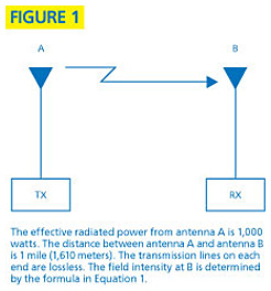
Figure 1 shows a transmitter connected to a half-wave dipole antenna and a receiver connected to a half-wave dipole antenna. The transmitter power is 1 kilowatt, or 1,000 watts. For this example, assume that the line losses are zero. The distance between the two antennas is 1 mile. The formula for calculating the field intensity in volts per meter, shown in Equation 1, assumes free-space propagation.

Since frequency is not part of the formula, we must assume that the calculated field intensity is independent of frequency. Plugging the numbers from the example above into Equation 1 yields a field intensity of 0.1375 V/m ( 137.5 mV/m) at point B, the receiving antenna.

This does not mean that an RF signal level of 137.5 mV appears across the antenna terminals (with a 50-ohm load connected). This is where frequency becomes a factor. The difference between the field intensity level at the antenna and the voltage appearing across the antenna terminals differs, in decibels, by the antenna factor. The antenna factor (for half-wave dipoles) is defined by the formula in Equation 2.

If we plug a frequency of 160 MHz into Equation 2 we find that the antenna factor is 12 dB/m. Recall that the field intensity at antenna B in Figure 1 is 137.5 mV/m. The signal level appearing across the antenna terminals and at the receiver input (assuming no line loss) is equal to the field intensity (e) minus the antenna factor (k), or 137.5 mV reduced by 12 dB. In terms of voltage, 12 dB represents a reduction equal to 25% of the original voltage, or 137.5/4 = 34.4 mV appearing across the antenna terminals and the input to the receiver. The formula for the signal level appearing across the antenna terminals is shown in Equation 3.

The antenna correction factor can be negative or positive. For a half-wave dipole, an antenna correction factor of 0 dB/m occurs at a frequency of approximately 40 MHz. Above 40 MHz, the correction factor is a positive value and below 40 MHz the correction factor is a negative value. For a given field intensity, a negative antenna factor will produce a higher signal level across the antenna terminals than a positive antenna factor. This is because a negative value substituted for k in Equation 3 produces a smaller denominator than would a positive value.

Field intensity often is expressed in terms of decibels referenced to 1 microvolt per meter and is written as dBu. That is, 0 dBu is 1 µV/m and 6 dBu is 2 µV/m. When the field intensity is stated in dBu it is easier to it convert to a signal level across the antenna terminals — this is done by simply adding or subtracting the antenna factor in dB/m. The formula in Equation 4 can be used for this purpose.

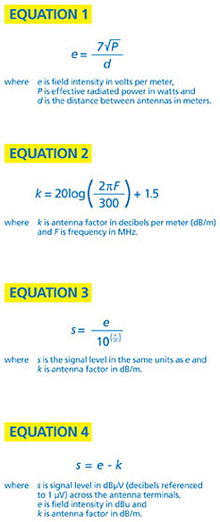
For example, if the field intensity at the antenna is stated as 12 dBu and the antenna factor is stated as 12 dB/m, the signal level in dBµV across the antenna terminals is 12 dBu – 12 dB/m = 0 dBµV, or simply 1 µV. Don’t confuse the use of the formulas in Equations 3 and 4. Equation 3 is used when the field intensity is in volts/meter or a related unit, such as mV/m or µV/m. Equation 4 is used when the field intensity is stated in dBu.

A simple way to convert between field intensity and signal level across the antenna terminals is just to remember that for a half-wave dipole the correction factor at 40 MHz is approximately 0 dB/m. Above 40 MHz, the half-wave dipole antenna correction factor is positive and below 40 MHz the antenna factor is negative. A positive correction factor means a lower signal level across the antenna terminals, while a negative correction factor means a higher signal level across the antenna terminals, for a given field intensity. For each octave (doubling of frequency) the antenna factor increases by 6 dB. Therefore, at 80 MHz the antenna factor for a half-wave dipole is 6 dB/m. If the field intensity is 20 dBu, the signal level across the antenna terminals is 20 – 6 = 14 dBµV, or 14 decibels above 1 microvolt, or approximately 5 µV. At 20 MHz, a given field intensity would produce a signal level across the half-wave dipole antenna terminals that is 2 times (6 dB greater than) that at 40 MHz.

Consider an antenna with a field intensity of 50 µV/m. The frequency is 160 MHz and the antenna is a simple half-wave dipole (0 dBd gain). Since this is 2 octaves above 40 MHz, the antenna factor is 6 + 6 = 12 decibels — a positive value. This means that the signal level across the antenna terminals is 12 decibels below the field intensity. Thus, the signal level at the antenna terminals is 50/4 = 12.5 µV. Now suppose that the antenna in Figure 2 has a gain of 6 dB referenced to a half-wave dipole, or a gain of 6 dBd. This would increase the signal level across the antenna terminals by 6 dB to 25 µV.

Further suppose that the antenna is connected to the receiver through a coaxial cable that has a loss of 2 dB. Assuming a signal level of 25 µV at the antenna terminals, what is the signal level at the receiver input? Table 1 provides a handy reference for making that determination. The gray section of the table correlates multiplication factors with equivalent decibel increases in power or voltage. For example, the first figure in the table indicates that a 25% increase in the power level equals an approximate increase of 1 dB. A 25% increase in the voltage level represents a 2 dB increase.

Meanwhile, the blue section of the table shows that the reciprocal of the multipliers in the gray section of the table will produce the same change in decibel level, but in the opposite direction. According to Table 1, a 2 dB signal voltage loss in the transmission line would translate to a multiplication factor of 0.8. Thus, a 25 µV signal level multiplied by 0.8 is equal to 20 µV at the input to the receiver.

Another convenient number to remember is that 1 microvolt equals -107 dBm (in a 50-ohm system). Let’s convert the 25 µV signal level at the antenna terminals to dBm by using the figures in Table 1. The ratio of the signal voltage to 1 microvolt is 25:1. Consulting Table 1 we find that we can get to 25 by using the multipliers of 10 (20 dB), 2 (6 dB) and 1.25 (2 dB) — 10 × 2 × 1.25 = 25. Adding the corresponding decibel figures, we get 20 + 6 + 2 = 28 dB. Thus, 25 µV is 28 dB above 1 µV. Now, simply add (algebraically) 28 dB and -107 dBm to get -79 dBm. This is the signal power at the antenna terminals. This is worth repeating: The term dBm represents signal power but easily can be converted to voltage as long as we know the system impedance. The signal power at the receiver input is reduced by the line loss of 2 dB to result in a signal level of -81 dBm.

When using the formula in Equation 2, remember that this applies only to a half-wave dipole (a gain of 0 dBd). Antennas that exhibit gain over a half-wave dipole will produce more signal voltage across the antenna terminals for a given field intensity level. Some antennas actually exhibit a loss compared to a half-wave dipole. For example, antennas used in pagers and handheld units may be quite lossy compared with a half-wave dipole and therefore produce much less signal voltage or power at the receiver input.

Harold Kinley is the author of three books, including Standard Radio Communications Manual and The Radioman’s Manual of RF Devices. A certified electronics technician, he holds an FCC First Class radio telephone license and an amateur radio operator Extra class license.

Related Stories

  • Deciphering RF units of measure
  • Ensuring RF is a multi-faceted task
  • Antenna phasing 101
MULTIPLIER ΔdB (POWER) ΔdB (VOLTAGE)
×1.25 +1 +2
×1.60 +2 +4
×2.0 +3 +6
×10 +10 +20
×1/1.25 (0.8) -1 -2
×1/1.60 (0.625) -2 -4
×1/2.0 (0.5) -3 -6
×1/10 (0.1) -10 -20
Tags: Call Center/Command Wireless Networks

Most Recent


  • Verizon officials highlight role of 5G tech for responders during IWCE keynote
    LAS VEGAS—As the public-safety sector continues to expand its use of data-intensive applications, developments in 5G can provide the low-latency, high-bandwidth connectivity to meet these needs, Verizon officials said yesterday during a keynote address at IWCE 2023. Bryan Schromsky, managing partner for Verizon’s public-sector unit, noted that the carrier plans to complete its deployment of […]
  • Rescue 42 launches miniCRD deployable for FirstNet
    Rescue 42 yesterday announced the launch of its miniCRD (mCRD) for FirstNet, which provides much of the functionality of the company’s Compact Rapid Deployable at a much lower cost.and in an even more portable form factor—two ruggedized cases that are about the size of checked luggage. Rescue 42 CEO Tim O’Connell said the mCRD (pictured […]
  • IWCE 2023
    Safer Buildings Coalition conducts annual event at IWCE 2023
    A common theme ran through the Safer Buildings Coalition’s annual meeting Monday night during IWCE 2023 at the Las Vegas Convention Center—strength through collaboration. “The perception is that the challenge is ‘out there,’ and someday, maybe the challenge will come here,” said Billy Bob Brown Jr., executive assistant director for emergency communications within the Cybersecurity […]
  • Good to know
    IWCE speakers debate state of public-safety interoperability
    LAS VEGAS—Achieving comprehensive interoperability for mission-critical communications used by U.S. public-safety agencies continues to be an elusive goal, according to speakers addressing the topic during a Monday session at the IWCE 2023 event in Las Vegas. Some view interoperability as the technical ability for one person to communicate with another, no matter what device or […]

Leave a comment Cancel reply

To leave a comment login with your Urgent Comms account:

Log in with your Urgent Comms account

Or alternatively provide your name, email address below:

Your email address will not be published. Required fields are marked *

Related Content

  • The battle over connected cars drags on
  • UK officials revamp ESN plans again, target Airwave-to-LTE transition for end of 2026
  • PSCR: Dereck Orr highlights features of June 21-24 virtual event
  • FirstNet buildout on pace for March 2023 completion, AT&T official says

Commentary


Updated: How ‘sidelink’ peer-to-peer communications can enhance public-safety operations

  • 1
27th February 2023

NG911 needed to secure our communities and nation

24th February 2023

How 5G is making cities safer, smarter, and more efficient

26th January 2023
view all

Events


UC Ezines


IWCE 2019 Wrap Up

13th May 2019
view all

Twitter


UrgentComm

Gallery: The last day of IWCE 2023 dlvr.it/SllQKJ

30th March 2023
UrgentComm

Video: Opening of the Expo Hall on day three of IWCE 2023 dlvr.it/SlkyNy

30th March 2023
UrgentComm

Verizon officials highlight role of 5G tech for responders during IWCE keynote dlvr.it/Slkh9n

30th March 2023
UrgentComm

Day three of IWCE 2023 features the opening of the Expo Hall dlvr.it/Slhgvr

30th March 2023
UrgentComm

Gallery: The Expo Hall opens on day three of IWCE 2023 dlvr.it/SlhfPT

29th March 2023
UrgentComm

Rescue 42 launches miniCRD deployable for FirstNet dlvr.it/SlgdtY

29th March 2023
UrgentComm

RT @IWCEexpo: 📽️ More sights from Day 2 at #IWCE23. It's been a fantastic start so far... Thanks to you! Tomorrow is another awesome spea…

29th March 2023
UrgentComm

RT @IWCEexpo: Ildefonso De La Cruz Morales, Principal Analyst-Critical Communications @OmdiaHQ takes the stage and kicks off tonight’s Keyn…

29th March 2023

Newsletter

Sign up for UrgentComm’s newsletters to receive regular news and information updates about Communications and Technology.

Expert Commentary

Learn from experts about the latest technology in automation, machine-learning, big data and cybersecurity.

Business Media

Find the latest videos and media from the market leaders.

Media Kit and Advertising

Want to reach our digital and print audiences? Learn more here.

DISCOVER MORE FROM INFORMA TECH

  • American City & County
  • IWCE
  • Light Reading
  • IOT World Today
  • Mission Critical Technologies
  • TU-Auto

WORKING WITH US

  • About Us
  • Contact Us
  • Events
  • Careers

FOLLOW Urgent Comms ON SOCIAL

  • Privacy
  • CCPA: “Do Not Sell My Data”
  • Cookie Policy
  • Terms
Copyright © 2023 Informa PLC. Informa PLC is registered in England and Wales with company number 8860726 whose registered and Head office is 5 Howick Place, London, SW1P 1WG.