Easier said than done
The design of a simple one-stage, low-noise RF amplifier is not as easy as it might seem. The RF design engineer has to take into account many factors and make compromises in the design of the final circuit. Some of the factors that are taken into account are: noise figure, gain, stability, bandwidth, linearity, operating point — such as collector-emitter voltage (VCE) and collector current (IC) — and input and output return loss (VSWR), as well as the physical construction of the circuit board.
RF design software and use of the Smith chart plays an important role in the RF design engineer’s task. There are many different RF design software packages that are available to the RF design engineer. This article presents a software package called QuickSmith (freeware) that allows the technician to get a glimpse into how a simple, one-stage low-noise RF amplifier is designed using S-parameters and noise parameters of a particular transistor.
First, we will examine the important design factors and then look at the design of a typical low-noise, single-stage RF amplifier.
Noise figure. It is important that the first stage of an RF amplifier chain have a low noise figure. If the first RF amplifier stage has a low noise figure along with significant gain, it will be the dominant factor in setting the system noise figure. Noise figure can be stated as a power ratio factor or in terms of decibels. The formula for noise factor is called the Friis formula. It is shown in Equation 1.
Noise figure usually is stated in decibels and is equal to 10 log(FT). It can be seen from Equation 1 why the first stage is the dominant factor in setting the system noise factor/figure if it has significant gain.
Gain. To provide amplification of the low-level input signal, the RF amplifier must have significant gain. As stated earlier, if the first stage RF transistor has high gain at a low noise figure, the system noise figure will be low. However, in the practical design of a low-noise RF amplifier, there is usually a tradeoff between gain and noise figure. When an amplifier is designed for maximum gain, the input and output impedance of the active device must be conjugately matched. The source impedance must be the conjugate of the input impedance of the active device (transistor) and the load impedance must be the conjugate of the output impedance of the transistor. Often, instead of stating the source and load impedance (complex), the reflection coefficient is given. The reflection coefficient is represented by Γ (gamma). The load reflection coefficient is ΓL and the source reflection coefficient is ΓS.
The source and load reflection coefficients each represent a unique complex impedance. The reflection coefficient (Γ) has both magnitude and angle. The reflection coefficient can be plotted on a Smith chart by finding the magnitude on the radial reflection coefficient scale (at the bottom of the chart) and drawing a line vertically to intersect the center line of the Smith chart. Then, a compass is used to draw a circle at this magnitude using the center of the Smith chart as the origin of the circle. Then, a line is drawn from the origin to the angle of the reflection coefficient. The intersection of this line and the circle is the impedance represented by the particular reflection coefficient.
S-parameters. S-parameters usually are found from the manufacturer’s data sheets. Table 1 shows the S-parameters for a transistor MRF571 that is biased to produce a VCE of 6 V and an IC of 5 mA. The S-parameters are shown for the transistor operating at 1,000 MHz at this particular operating point. To briefly explain S-parameters, S11 is the input reflection coefficient, S22 is the output reflection coefficient, S21 is the voltage gain from input to output and S12 is the isolation between output and input. If S11 is expressed in decibels, it represents the input return loss. If S22 is expressed in decibels, it represents the output return loss. In fact, all S-parameters may be expressed in decibels and it is common to find data sheets in which S-parameters are expressed in decibels. Often, S2P files (two-port S-parameters) are expressed in decibels.
A two-port device can be analyzed using the S-parameters. If the isolation figure (S12) of the transistor is 0 (meaning complete isolation in the reverse direction) the input and output matching circuit of the transistor can be designed independently. However, in a practical transistor the isolation (S12) is never 0, but is some small fraction. Thus, the load impedance affects the input impedance and vice versa. This means that to achieve maximum gain, the input and output circuits must be simultaneously conjugate-matched.
Noise parameters. Table 1 shows the noise parameters for the MRF571 transistor operating at a frequency of 1,000 MHz and biased to produce VCE = 6 V and IC = 5 mA. This is also found in the manufacturer’s (Motorola) data sheets. The minimum noise figure is 1.5 dB. The minimum noise figure is achieved when the source reflection coefficient (ΓS) is equal to ΓOPT. Notice in Table 1 that ΓOPT is 0.48@134°. The equivalent noise resistance (RN) is 7.5 Ω.
Stability. The stability factor of a transistor is usually provided along with the S-parameters. If the stability factor isn’t given it can be calculated from the S-parameters. The stability factor referenced here is called the Rollett stability factor. The Rollett stability factor (k) must be greater than 1 (k>1) for the transistor to be unconditionally stable. Another factor called delta (∆ or DS) must be less than 1 (∆<1) for the transistor to be unconditionally stable. Unconditional stability means that the transistor will not oscillate under any source or load impedance. Typically, it is good advice to avoid using transistors that are not unconditionally stable. If you must use a transistor that is not unconditionally stable, you must choose the source and load impedances carefully. Typical RF design software will display stability circles on or around the Smith chart. The area of stable operation can be inside or outside the stability circle. Typically, if the center of the Smith chart (50 + j0 ohms) is outside the stability circle, then the area outside the stability circle is in the stable region. If the center of the Smith chart (50 + j0 ohms) is inside the stability circle then the area inside the stability circle is in the stable region. For unconditionally stable transistors, the entire Smith chart will be in the stable region. For conditionally stable transistors, part of the Smith chart will be in the unstable region.
Example. A simple low-noise, single-stage RF amplifier (1,000 MHz) is designed using freeware created by QuickSmith, which can be downloaded at www.nathaniyer.com. This circuit employs the Motorola MRF571 transistor in a common emitter configuration. The S-parameters and noise parameters for this transistor are shown in Table 1 for a frequency of 1,000 MHz at an operating point where IC = 5 mA and VCE = 6 V.
Using the QuickSmith software, click on Amplifier Design and then on S-Parameter Design/Analysis. Enter the S-parameters and noise parameters from Table 1 for the MRF571 transistor. See Figure 1A. After you enter the S-parameters, click on the Stability button. If k is greater than 1 and delta is less than 1, the transistor is unconditionally stable. This means that the transistor will not oscillate under any input or output impedance conditions. Since the transistor is unconditionally stable, there is no need to draw the stability circle on the Smith chart. In short, any location on the Smith chart is safe to use. Next, enter the noise parameters from Table 1. (Figure 1B.)

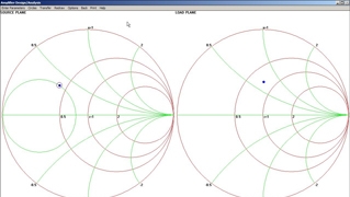
Next, click on the Circles button and check available gain and noise circles. The noise and available gain circles appear on the display. See Figure 2. This screen shot was taken after the green constant gain circle was adjusted to 10.7dB, the noise figure circle adjusted to 1.505dB and the input reflection coefficient set to ΓOPT (0.48@134°). The blue dot located at the center of this noise circle represents the minimum noise figure—1.5dB.

Note that the source impedance ZS associated with ΓOPT (0.48 @ 134°) is 20.3 + j18.2 ohms. Thus, looking from the base of the transistor toward the source we must “see” a source impedance of 20.3 + j18.2 ohms. QuickSmith comes in handy again in designing a transformation network such that the 50Ω source impedance is transformed to 20.3 + j18.2 ohms. On the QuickSmith toolbar click on Transfer and select Source Impedance. Then, click on Back on the toolbar. The display should look like Figure 3 with the Smith chart in the left pane and a circuit design tool in the right pane. Notice that the load impedance is set to the conjugate of the source impedance (ZS) shown in Figure 2. Note that in Figure 3 there are no components placed on the schematic and the input impedance is the same as the load impedance, 20.3 – j18.2 ohms. The object is to place components on the schematic and adjust the values until the blue dot on the Smith chart is moved directly over the center—representing a purely resistive 50-ohm impedance. Components can be placed on the schematic by simply dragging and dropping the component icons where desired in the circuit.
Through some experimentation we came up with the matching circuit shown in Figure 4 consisting of one inductor and one capacitor. Notice that the input (right side) is nearly a pure resistance of 50Ω and the dot is at the center of the Smith chart. But wait! According to Figure 2 the output of the transistor should see an impedance of 20.3 + j18.2 ohms. (Figure 5) Here, the load (RX) represents the 50Ω source impedance and the input indicates 20.3 + j18.2 ohms (not exactly, but very close) — this is what the transistor “sees” as its source impedance. Thus, the impedance transformation is complete. In like manner, the output impedance is transformed. Important!! Be sure to set the frequency under the “Assign Values” button on the toolbar. It makes a difference!

In designing a simple single-stage, low-noise RF transistor amplifier, the RF design engineer must make tradeoffs between noise figure, gain, available components, board layout, parts count and a host of other considerations. RF design software has become an essential tool. As shown in this simple example, maximum gain and minimum noise figure don’t occur simultaneously. Often, several decibels of gain might be sacrificed to achieve the desired noise figure. RF design software allows the engineer to make quick “what-if” comparisons. Here the design target was minimum noise figure. This meant that some gain was sacrificed due to input mismatch loss. The input was noise-matched while the output was conjugately impedance-matched. Sometimes, the design engineer may look for a compromise between minimum noise and maximum gain — some gain is picked up at the expense of increased noise figure.

Related Stories