Soak up the sun
Correction: An earlier version of this story incorrectly reported the size of silicon cells. Common cells are square with dimensions 10 cm × 10 cm or 15 cm × 15 cm.
Often the best repeater sites are located on remote mountain peaks where it is cost-prohibitive to provide commercial power. Typically, solar is the preferred alternative at these locations. The purpose of this article is to review solar cell technology, describe some recent advances, and introduce the methods and calculations used to design solar power systems for communications sites.
History of the photovoltaic cell
A solar cell is more accurately a photovoltaic cell. Certain materials exhibit the photovoltaic effect, which occurs when light releases electrons from their atoms, causing them to flow in one direction through the material. In essence, a photovoltaic cell is a direct current (DC) source that functions similarly to a semiconductor diode. The photovoltaic effect first was discovered in 1839 by French physicist A.E. Becquerel, but the first solar cell was not built until 1883, when Charles Fritts fabricated a selenium cell with a thin layer of gold to create terminals. Photovoltaic cells did not become practical until 1954, when scientists at Bell Labs accidentally discovered that silicon doped with certain impurities was very sensitive to light. Vanguard I was the first satellite to employ solar cells when it was launched in 1958.
The physics of photovoltaic cells and recent advances
The voltage from a solar cell depends on the semiconductor material. More than 90% of the solar cells sold commercially are silicon-based, and the open circuit cell voltage in this case is 0.5 volts. Voltage is only weakly dependent on light intensity, but current increases with higher radiation. A 100 cm2 silicon cell radiated by 1 kw/m2 will produce about 2 amps. Most silicon cells are approximately 10 cm square with 15 cm square cells being introduced recently. Cells employ a transparent anti-reflection film that protects the cell and reduces losses due to reflection. Photovoltaic cells work best at lower temperatures. Capacity degrades at a rate of roughly 0.5%/°C for crystalline silicon cells.
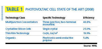
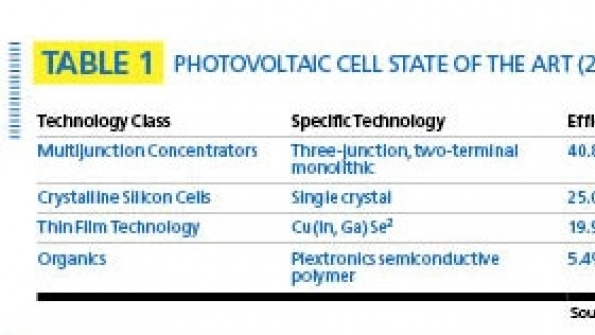
Recent research conducted at the National Renewable Energy Lab (NREL) in Golden, Colo., and at other university and corporate laboratories, is focused on organics, thin-film technology and multi-junction concentrators. Organic cells employ polymers similar to plastics. Organics exhibit poor efficiency but have the advantage of low cost and the ability to print the material onto surfaces like ink on paper. Thin-film technologies are lightweight and flexible, and have moderate efficiency. A concentrating photovoltaic system uses a large area of lenses or mirrors to focus sunlight onto a small area of photovoltaic cells. Needless to say, such systems are prohibitively expensive, but some have achieved efficiencies of about 40%, significantly better than the other options. (See Table 1).
Designing solar arrays for remote sites
The main purpose of the solar array is to provide enough kilowatt-hours of energy over the worst-case 24-hour period to charge the batteries that provide the real power for the site. The solar array essentially is a battery-charging system. The required size of the solar array (in square meters) depends on the power requirements of the site, solar-cell efficiency, site latitude, climate, orientation of the array, ambient temperatures and any shadowing caused by local vegetation, terrain or manmade obstructions.

Solar cells are surprisingly inefficient. With direct exposure, the sun radiates 1 kw per square meter, but the best practical solar cells are less than 20% efficient. When one factors in other elements such as short winter days, northern latitudes, indirect exposure and cloud cover, it is not uncommon for an array to require tens of square meters for every kilowatt of site load.
Most of the calculations required to design the solar array are within the capability of the radio technician or engineer, with the exception of the solar radiation, which has units of kwh/m2/day. Solar radiation is a complicated function of latitude, time of year, terrain and climate. Fortunately, the NREL provides a free, web-based calculator that calculates average solar radiation per month for any location in the United States. (See www.pvwatts.org.) As one would expect, solar radiation is greatest in the desert southwest in summer and least at northern latitudes in winter, with Alaska being especially poor in the winter. Figure 1 shows the annual average solar radiation for the United States. This figure is a bit misleading for the system designer because solar-array design is controlled by the worst-case winter day, not the annual average. Solar cells practically are worthless in the winter in northern Alaska, where the sun does not rise for six months. Fortunately, the NREL calculator computes the average solar radiation by month, not just year. A sample output for Denver is shown in Table 2.
Design example
Let’s consider a small station near Denver that has an average power requirement of 400 watts. The sun follows a diurnal cycle, i.e., we have to store enough energy during daylight hours to last through the night. The energy-storage requirement is 400 watts × 24 hours, or 9.6 kwh. Solar arrays come in standard sizes; for the purpose of this exercise, let’s start with a 4 kw array. From Table 2, we see that the worst-case month in Denver is November and that the average energy provided per day in that month is 403/30 = 13.4 kwh. Table 2 gives mean values, but the NREL says monthly totals can vary by as much as 30% from the mean. Daily values will vary even more, but daily values were not readily available. Fortunately, the NREL also publishes minimum, maximum and standard-deviation values. The minimum value for November is 15% lower than the average, which happens to be 2.5 standard deviations. If we assume a normal distribution, 2.5 standard deviations correspond to a 99.4% system availability. However, the annual system availability is greater, because we are designing for the worst-case month. If we de-rate by 15%, we get 11.4 kwh, which is sufficient to meet our requirement of 9.6 kwh (400 watts average power).
Assuming an efficiency of 14%, our 4 kw array will occupy 28.6 square meters, the size of a large family room. As a practical matter, such an array typically is constructed from 20 smaller (200 watt) arrays. Pricing for a complete 4 kw system with inverter is about $18,500.
The previous exercise is a bit crude. A more sophisticated design would be based on the worst-case run of cloudy winter days. In other words, the system may be called upon to store enough energy for multiple consecutive days, not just one.
Installation checklist
To achieve optimal performance, it is important to adhere to a few important guidelines. Most solar arrays are fixed installations and should therefore be designed to point directly at the sun at noon on winter days. Thus, the array should point due south for sites in the northern hemisphere. The winter rule of thumb for tilt angle relative to the horizontal is to multiply the site latitude by 0.9 and add 30 degrees. If the panels are accessible year round and have adjustable tilt, one can squeeze some additional energy out of the system by adjusting the tilt seasonally. This might be desirable, for example, if the system runs an air conditioner in summer and the summer load taxes the system more heavily than winter, despite the greater average radiation in summer.
It also is important to eliminate all shadowing of the solar cells. Shadowing of even a small area can affect the entire array, because the cells are connected in series and one shadowed cell can choke off current for an entire row of cells.
Finally, the solar array should have good ventilation to minimize cell temperature. Solar cell output decreases with increasing temperature.
Jay Jacobsmeyer is president of Pericle Communications Co., a consulting engineering firm located in Colorado Springs, Colo. He holds bachelor’s and master’s degrees in electrical engineering from Virginia Tech and Cornell University, respectively, and has more than 25 years experience as a radio-frequency engineer.
Related Stories


