https://urgentcomm.com/wp-content/themes/ucm_child/assets/images/logo/footer-logo.png
  • Home
  • News
  • Multimedia
    • Back
    • Multimedia
    • Video
    • Podcasts
    • Galleries
  • Commentary
    • Back
    • Commentary
    • Urgent Matters
    • View From The Top
    • All Things IWCE
    • Legal Matters
  • Resources
    • Back
    • Resources
    • Events
    • Webinars
    • White Papers
    • Reprints & Reuse
  • IWCE
    • Back
    • IWCE
    • Conference
    • Special Events
    • Exhibitor Listings
    • Premier Partners
    • Floor Plan
    • Exhibiting Information
    • Register for IWCE
  • About Us
    • Back
    • About Us
    • Contact Us
    • Advertise
    • Terms of Service
    • Privacy Statement
    • Cookies Policy
  • Related Sites
    • Back
    • American City & County
    • IWCE
    • Light Reading
    • IOT World Today
    • Mission Critical Technologies
    • Microwave/RF
    • T&D World
    • TU-Auto
  • In the field
    • Back
    • In the field
    • Broadband Push-to-X
    • Internet of Things
    • Project 25
    • Public-Safety Broadband/FirstNet
    • Virtual/Augmented Reality
    • Land Mobile Radio
    • Long Term Evolution (LTE)
    • Applications
    • Drones/Robots
    • IoT/Smart X
    • Software
    • Subscriber Devices
    • Video
  • Call Center/Command
    • Back
    • Call Center/Command
    • Artificial Intelligence
    • NG911
    • Alerting Systems
    • Analytics
    • Dispatch/Call-taking
    • Incident Command/Situational Awareness
    • Tracking, Monitoring & Control
  • Network Tech
    • Back
    • Network Tech
    • Interoperability
    • LMR 100
    • LMR 200
    • Backhaul
    • Deployables
    • Power
    • Tower & Site
    • Wireless Networks
    • Coverage/Interference
    • Security
    • System Design
    • System Installation
    • System Operation
    • Test & Measurement
  • Operations
    • Back
    • Operations
    • Critical Infrastructure
    • Enterprise
    • Federal Government/Military
    • Public Safety
    • State & Local Government
    • Training
  • Regulations
    • Back
    • Regulations
    • Narrowbanding
    • T-Band
    • Rebanding
    • TV White Spaces
    • None
    • Funding
    • Policy
    • Regional Coordination
    • Standards
  • Organizations
    • Back
    • Organizations
    • AASHTO
    • APCO
    • DHS
    • DMR Association
    • ETA
    • EWA
    • FCC
    • IWCE
    • NASEMSO
    • NATE
    • NXDN Forum
    • NENA
    • NIST/PSCR
    • NPSTC
    • NTIA/FirstNet
    • P25 TIG
    • TETRA + CCA
    • UTC
Urgent Communications
  • NEWSLETTER
  • Home
  • News
  • Multimedia
    • Back
    • Video
    • Podcasts
    • Galleries
  • Commentary
    • Back
    • All Things IWCE
    • Urgent Matters
    • View From The Top
    • Legal Matters
  • Resources
    • Back
    • Events
    • Webinars
    • White Papers
    • Reprints & Reuse
    • UC eZines
  • IWCE
    • Back
    • Conference
    • WHY ATTEND
    • Exhibitor Listings
    • Floor Plan
    • Exhibiting Information
    • Registration Opens April 2019-Join Our Mailing List
  • About Us
    • Back
    • About Us
    • Contact Us
    • Advertise
    • Terms of Service
    • Privacy Statement
    • Cookies Policy
  • Related Sites
    • Back
    • American City & County
    • IWCE
    • Light Reading
    • IOT World Today
    • TU-Auto
  • newsletter
  • In the field
    • Back
    • Internet of Things
    • Broadband Push-to-X
    • Project 25
    • Public-Safety Broadband/FirstNet
    • Virtual/Augmented Reality
    • Land Mobile Radio
    • Long Term Evolution (LTE)
    • Applications
    • Drones/Robots
    • IoT/Smart X
    • Software
    • Subscriber Devices
    • Video
  • Call Center/Command
    • Back
    • Artificial Intelligence
    • NG911
    • Alerting Systems
    • Analytics
    • Dispatch/Call-taking
    • Incident Command/Situational Awareness
    • Tracking, Monitoring & Control
  • Network Tech
    • Back
    • Cybersecurity
    • Interoperability
    • LMR 100
    • LMR 200
    • Backhaul
    • Deployables
    • Power
    • Tower & Site
    • Wireless Networks
    • Coverage/Interference
    • Security
    • System Design
    • System Installation
    • System Operation
    • Test & Measurement
  • Operations
    • Back
    • Critical Infrastructure
    • Enterprise
    • Federal Government/Military
    • Public Safety
    • State & Local Government
    • Training
  • Regulations
    • Back
    • Narrowbanding
    • T-Band
    • Rebanding
    • TV White Spaces
    • None
    • Funding
    • Policy
    • Regional Coordination
    • Standards
  • Organizations
    • Back
    • AASHTO
    • APCO
    • DHS
    • DMR Association
    • ETA
    • EWA
    • FCC
    • IWCE
    • NASEMSO
    • NATE
    • NXDN Forum
    • NENA
    • NIST/PSCR
    • NPSTC
    • NTIA/FirstNet
    • P25 TIG
    • TETRA + CCA
    • UTC
acc.com

Wireless Networks


Making gains in the vertical plane

Making gains in the vertical plane

Some theory and a summary of recent advances in base station antennas.
  • Written by Urgent Communications Administrator
  • 1st March 2010

Base station (i.e., repeater site) antennas tend to be vertical linear arrays of dipole or similar elements. A vertical array is preferred because the array creates gain in the vertical plane, thereby focusing energy toward the horizon where it is needed. If a directional antenna is required, a combination of a vertical array and a reflector is used to focus energy into a narrow sector, typically 65, 90 or 120 degrees wide at the 3 dB points of the azimuth pattern. In this article, we will examine some of the characteristics of antenna arrays for base-station applications and review some recent technology advances, including smart antennas and multiple-input, multiple-output (MIMO) antenna arrays. Let’s start with antenna patterns.

Antenna patterns of vertical arrays

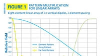
In the far field, the pattern factor, f(?), is the product of the element pattern factor, fe(?), and the array pattern factor, fa(?). See Equation 1. One of the most widely used antenna elements is the half-wavelength dipole. The element pattern for a half-wave dipole — obtained from Equation 2 — when rotated around a vertical axis forms the “doughnut” pattern familiar to most readers. The array factor for a uniformly excited linear array can be obtained from Equations 3 and 4. By uniformly excited, we mean that each element is fed in phase. Sometimes it is desirable to alter the element phase to create null fill or electrical beam tilt at the expense of some loss in gain.

An example of the use of Equations 1 through 4 is shown in Figure 1, where we have plotted the element, array and antenna patterns for an eight-element linear array of vertical half-wave dipoles.

For directional antennas, the azimuth pattern is as important as the vertical pattern. One of the important characteristics of the azimuth pattern is the front-to-back ratio, which is the difference (in dB) between the antenna gain in the main antenna lobe and the gain directly behind the antenna. Front-to-back ratio is important for co-channel interference rejection and mitigation of time delay interference (TDI) in simulcast networks. See Figure 2 for the azimuth pattern of a typical panel antenna.

Gain

The two-dimensional antenna patterns in the previous section give some clues to the antenna gain, but gain is measured in three dimensions and is not found directly from the antenna pattern. Antenna gain is defined in Equation 5.

In general, antenna gain is difficult to calculate except for the simplest antenna elements and arrays. For the special case of a uniformly fed linear array of half-wave dipoles spaced one wavelength apart, the gain of the array is equal to N times the gain of a dipole, where N is the number of elements in the array. For example, an 8-element array has a gain of 8*1.64 = 13.1, or 11.2 dBi. In land mobile radio, it is customary to specify gain relative to a half-wave dipole. In this case, the gain is simply equal to the number of dipole elements, which in this example is 8 or 9 dBd.

Decreasing the element spacing to less than one wavelength sometimes is desirable, because it creates favorable changes in the pattern side lobes, but the gain always will be less (at least for dipole elements). In other words, the number of array elements alone does not determine the gain; the length of the array is equally important.

Beamwidth

The horizontal and vertical beamwidth (measured at the 3 dB pattern points) are major determinants of how well the antenna will cover the service area. Gain and beamwidth are tightly coupled; the higher the gain, the narrower the beamwidth. For tall sites, high-gain omnidirectional antennas rarely are advisable because narrow beamwidth means the antenna will overshoot the service area.

Beam tilt

Beam tilt comes in two flavors: electrical and mechanical. Electrical beam tilt is created by altering the phase between the upper half and lower half of the antenna array. Electrical beam tilt creates the same tilt in all directions. Mechanical beam tilt, on the other hand, varies from a maximum value in the tilt direction to 0° at +/- 90° azimuth to maximum uptilt behind the antenna. The expression (without derivation) for the mechanical beam tilt, ?, at an arbitrary angle, a, from the center of the beam when the beam tilt at center is ? degrees is obtained from Equation 6.

For example, if the tilt at the main lobe is ? = -3°, the beam tilt at the edge of beam for a 120-degree panel antenna (at a = +/- 60°) is -1.5°. Total beam tilt is simply the sum of electrical beam tilt and mechanical tilt. Figure 3 depicts a plot of the combined beam tilt as a function of azimuth angle, a, for an antenna with -2° electrical tilt and -1.5° mechanical tilt in the direction of the main pattern lobe.

Many antennas are ordered with no beam tilt and zero beam tilt is probably harmless when the vertical beamwidth is greater than 15 degrees, but high-gain antennas (> 6 dBd) almost always should have some downward beam tilt because radio energy directed above the horizon is wasted. Creative combinations of electrical beam tilt and mechanical beam tilt sometimes are used to limit co-channel interference in a direction away from the service area (in front of the antenna) while simultaneously providing good coverage in the service area (behind the antenna). Beam tilt also is a powerful tool in simulcast network design because it helps limit TDI within the network.

Bandwidth

Antenna bandwidth can be defined in several ways, but usually it is defined by a maximum Voltage Standing Wave Ratio (VSWR). Often, a maximum VSWR of 1.5 is used. Several antenna characteristics affect bandwidth, including the type of element used and the size of the conductors. Generally speaking, the wider the conductor, the greater the bandwidth. When wide bandwidth is needed, log-periodic elements sometimes are used rather than dipoles.

The type of array feed also affects bandwidth. A series feed has narrower bandwidth because the phase difference between the center frequency and the edge of the bandwidth frequency increases proportionally to the number of elements. A branch feed, on the other hand, uses power dividers and equal length transmission lines to each element, thereby limiting the phase error between the center frequency and the bandwidth edge. A typical antenna bandwidth is 12% of the center frequency.

Polarization

In many land mobile radio bands, the FCC requires vertical polarization, so the licensee has no polarization option. Cellular phone operators, on the other hand, have no limits on polarization and 45-degree “slant” polarization is common, using two antenna arrays in one radome, with the antenna elements orthogonal to each other and at a 45-degree angle to the vertical. One of the advantages of polarization diversity is that it limits the number of required antennas, reducing the wind load on the tower and making zoning approval more likely. For more on antenna diversity, see the June 2006 issue of Mobile Radio Technology.

Passive Intermodulation Rejection (PIM)

Transmit antennas must handle high power and multiple simultaneous frequencies, making intermodulation a key concern. Antenna manufacturers typically design for -150 dBc, 3rd-order PIM rejection with two, 20 W transmitters applied at the connector. Many manufacturers claim to PIM test every antenna before it is shipped, but low-PIM design is more important than factory tests. Low-PIM design is important because vibration, temperature variations, corrosion and other environmental effects can degrade an antenna’s PIM performance over time. Good low-PIM designs employ 7/16 DIN connectors, no coaxial cable harnesses, all-stripline construction, welding rather than fasteners, no dissimilar metals and the use of mated materials with similar temperature-expansion coefficients.

Recent advances

Smart antennas enhance coverage through range extension and hole-filling. Definitions vary, but for our purposes, a smart antenna is an adaptive antenna array used to determine direction of arrival and to perform electronic beamforming. Smart base station antennas allow the system to tailor the pattern for the most disadvantaged user, thereby improving service-area reliability without adding new sites. Smart antennas have been touted as the next big thing in the cellular phone industry for more than 15 years, but high costs and logistical hassles created by large antenna arrays have prevented widespread adoption to date.

MIMO antenna arrays are part of the IEEE 802.11n Wi-Fi standard and they likely will appear in 700 MHz, Long Term Evolution (LTE) networks. In a MIMO system, a transmitter sends multiple simultaneous bit streams to multiple antennas. The distant end receiver collects signals from multiple receive antennas. MIMO networks employ the principles of pre-coding, spatial multiplexing and diversity coding to dramatically boost throughput.

Jay Jacobsmeyer is president of Pericle Communications Co., a consulting engineering firm located in Colorado Springs, Colo. He holds bachelor’s and master’s degrees in electrical engineering from Virginia Tech and Cornell University, respectively, and has more than 25 years experience as a radio-frequency engineer.

Related Stories

  • Antenna diversity is a good thing
  • Why can’t we talk? It’s the interference
  • MIMO’s future becomes less certain
  • Base station planning isn’t simple
Tags: Call Center/Command Wireless Networks

Related


  • Using data to improve emergency response resources in healthcare arena
    The ability for a COVID-19 outbreak to swiftly consume emergency response resources has emphasized the need for accurate and timely data reporting as a central component of the pandemic response effort. Continuous analysis of data collected is producing concerning results for response leaders, as new variants of the virus are discovered, and the United States […]
  • 3 security flaws in devices and IoT that need fixing
    Rapid changes in how Internet of Things (IoT) devices around us interact with each other have created a landscape defined by unprecedented security vulnerabilities. There are three main security concerns with them and some possible fixes. In December 2020, Forescout identified 33 vulnerabilities impacting four open source TCP/IP stacks. These are used by millions of devices around […]
  • Newscan: America’s creaky payment infrastructure is showing cracks
    Newscan: America’s creaky payment infrastructure is showing cracks
    Web Roundup Items from other news organizations America’s creaky payment infrastructure is showing cracks Woman safe after texting 911 to report being held against her will in semi truck Experts say $15 billion could fix broken 911 system, saving lives and money Progressives want Joe Biden to go big for FCC chair. Does Joe Biden? […]
  • California PD: ‘Game-changing’ Live911 streaming of emergency calls accelerates responses
    Police officers in the city of Clovis, Calif., are able to respond more quickly to incidents—saving lives and property—because they use the Live911 application developed by HigherGround to listen to the audio from 911 calls near their location, according to a Clovis police official. Jim Munro, a lieutenant in the Clovis Police Department, said the […]

Leave a comment Cancel reply

To leave a comment login with your Urgent Comms account:

Log in with your Urgent Comms account

Or alternatively provide your name, email address below:

Your email address will not be published. Required fields are marked *

Related Content

  • Newscan: SolarWinds CEO recommends liability protections for sharing information about incidents
  • Mission Critical Partners: New CEO Darrin Reilly discusses acquisition, company growth and outlook
  • Spectrum coordinators initiate submittal of new T-Band applications
  • Hiding in plain sight: What the SolarWinds attack revealed about efficacy

Commentary


Ransomware? Let’s call it what it really is: extortionware

21st February 2021

Redefining communications for today’s mobile workforces

18th February 2021

Hi-tech sewer can help safeguard public health, environment and economies

18th February 2021
view all

Events


UC Ezines


IWCE 2019 Wrap Up

13th May 2019
view all

Twitter


UrgentComm

Microsoft adopted ‘aggressive’ strategy for sharing SolarWinds Attack intel dlvr.it/Rv9vmp

8th March 2021
UrgentComm

How SolarWinds busted up our assumptions about code signing dlvr.it/Rv25kB

5th March 2021
UrgentComm

Senate American Rescue plan calls for more than $60 million in direct aid for counties dlvr.it/Rv1wGF

5th March 2021
UrgentComm

NTIA seeks potential new FirstNet Authority board members dlvr.it/Rv0YfL

5th March 2021
UrgentComm

Smart-building projects target energy efficiency as launchpad to health and safety dlvr.it/RtyhRY

4th March 2021
UrgentComm

ESN official hints at potentially costly new timeline for UK public-safety broadband project dlvr.it/Rttvzj

3rd March 2021
UrgentComm

Ericsson, Huawei, AT&T attending Mobile World Congress in June, others not so sure dlvr.it/RtrtT2

3rd March 2021
UrgentComm

Newscan: Klobuchar calls on Congress to get serious on tech reform dlvr.it/RtqByn

2nd March 2021

Newsletter

Sign up for UrgentComm’s newsletters to receive regular news and information updates about Communications and Technology.

Expert Commentary

Learn from experts about the latest technology in automation, machine-learning, big data and cybersecurity.

Business Media

Find the latest videos and media from the market leaders.

Media Kit and Advertising

Want to reach our digital and print audiences? Learn more here.

DISCOVER MORE FROM INFORMA TECH

  • American City & County
  • IWCE
  • Light Reading
  • IOT World Today
  • Mission Critical Technologies
  • Microwave/RF
  • T&D World
  • TU-Auto

WORKING WITH US

  • About Us
  • Contact Us
  • Events
  • Careers

FOLLOW Urgent Comms ON SOCIAL

  • Privacy
  • CCPA: “Do Not Sell My Data”
  • Cookies Policy
  • Terms
Copyright © 2021 Informa PLC. Informa PLC is registered in England and Wales with company number 8860726 whose registered and Head office is 5 Howick Place, London, SW1P 1WG.
This website uses cookies, including third party ones, to allow for analysis of how people use our website in order to improve your experience and our services. By continuing to use our website, you agree to the use of such cookies. Click here for more information on our Cookie Policy and Privacy Policy.
X