https://urgentcomm.com/wp-content/themes/ucm_child/assets/images/logo/footer-new-logo.png
  • Home
  • News
  • Multimedia
    • Back
    • Multimedia
    • Video
    • Podcasts
    • Galleries
    • IWCE’s Video Showcase
    • Product Guides
  • Commentary
    • Back
    • Commentary
    • Urgent Matters
    • View From The Top
    • All Things IWCE
    • Legal Matters
  • Resources
    • Back
    • Resources
    • Webinars
    • White Papers
    • Reprints & Reuse
  • IWCE
    • Back
    • IWCE
    • Conference
    • Special Events
    • Exhibitor Listings
    • Premier Partners
    • Floor Plan
    • Exhibiting Information
    • Register for IWCE
  • About Us
    • Back
    • About Us
    • Contact Us
    • Advertise
    • Terms of Service
    • Privacy Statement
    • Cookie Policy
  • Related Sites
    • Back
    • American City & County
    • IWCE
    • Light Reading
    • IOT World Today
    • Mission Critical Technologies
    • TU-Auto
  • In the field
    • Back
    • In the field
    • Broadband Push-to-X
    • Internet of Things
    • Project 25
    • Public-Safety Broadband/FirstNet
    • Virtual/Augmented Reality
    • Land Mobile Radio
    • Long Term Evolution (LTE)
    • Applications
    • Drones/Robots
    • IoT/Smart X
    • Software
    • Subscriber Devices
    • Video
  • Call Center/Command
    • Back
    • Call Center/Command
    • Artificial Intelligence
    • NG911
    • Alerting Systems
    • Analytics
    • Dispatch/Call-taking
    • Incident Command/Situational Awareness
    • Tracking, Monitoring & Control
  • Network Tech
    • Back
    • Network Tech
    • Interoperability
    • LMR 100
    • LMR 200
    • Backhaul
    • Deployables
    • Power
    • Tower & Site
    • Wireless Networks
    • Coverage/Interference
    • Security
    • System Design
    • System Installation
    • System Operation
    • Test & Measurement
  • Operations
    • Back
    • Operations
    • Critical Infrastructure
    • Enterprise
    • Federal Government/Military
    • Public Safety
    • State & Local Government
    • Training
  • Regulations
    • Back
    • Regulations
    • Narrowbanding
    • T-Band
    • Rebanding
    • TV White Spaces
    • None
    • Funding
    • Policy
    • Regional Coordination
    • Standards
  • Organizations
    • Back
    • Organizations
    • AASHTO
    • APCO
    • DHS
    • DMR Association
    • ETA
    • EWA
    • FCC
    • IWCE
    • NASEMSO
    • NATE
    • NXDN Forum
    • NENA
    • NIST/PSCR
    • NPSTC
    • NTIA/FirstNet
    • P25 TIG
    • TETRA + CCA
    • UTC
Urgent Communications
  • NEWSLETTER
  • Home
  • News
  • Multimedia
    • Back
    • Video
    • Podcasts
    • Omdia Crit Comms Circle Podcast
    • Galleries
    • IWCE’s Video Showcase
    • Product Guides
  • Commentary
    • Back
    • All Things IWCE
    • Urgent Matters
    • View From The Top
    • Legal Matters
  • Resources
    • Back
    • Webinars
    • White Papers
    • Reprints & Reuse
    • UC eZines
    • Sponsored content
  • IWCE
    • Back
    • Conference
    • Why Attend
    • Exhibitor Listing
    • Floor Plan
    • Exhibiting Information
    • Join the Event Mailing List
  • About Us
    • Back
    • About Us
    • Contact Us
    • Advertise
    • Cookie Policy
    • Terms of Service
    • Privacy Statement
  • Related Sites
    • Back
    • American City & County
    • IWCE
    • Light Reading
    • IOT World Today
    • TU-Auto
  • newsletter
  • In the field
    • Back
    • Internet of Things
    • Broadband Push-to-X
    • Project 25
    • Public-Safety Broadband/FirstNet
    • Virtual/Augmented Reality
    • Land Mobile Radio
    • Long Term Evolution (LTE)
    • Applications
    • Drones/Robots
    • IoT/Smart X
    • Software
    • Subscriber Devices
    • Video
  • Call Center/Command
    • Back
    • Artificial Intelligence
    • NG911
    • Alerting Systems
    • Analytics
    • Dispatch/Call-taking
    • Incident Command/Situational Awareness
    • Tracking, Monitoring & Control
  • Network Tech
    • Back
    • Cybersecurity
    • Interoperability
    • LMR 100
    • LMR 200
    • Backhaul
    • Deployables
    • Power
    • Tower & Site
    • Wireless Networks
    • Coverage/Interference
    • Security
    • System Design
    • System Installation
    • System Operation
    • Test & Measurement
  • Operations
    • Back
    • Critical Infrastructure
    • Enterprise
    • Federal Government/Military
    • Public Safety
    • State & Local Government
    • Training
  • Regulations
    • Back
    • Narrowbanding
    • T-Band
    • Rebanding
    • TV White Spaces
    • None
    • Funding
    • Policy
    • Regional Coordination
    • Standards
  • Organizations
    • Back
    • AASHTO
    • APCO
    • DHS
    • DMR Association
    • ETA
    • EWA
    • FCC
    • IWCE
    • NASEMSO
    • NATE
    • NXDN Forum
    • NENA
    • NIST/PSCR
    • NPSTC
    • NTIA/FirstNet
    • P25 TIG
    • TETRA + CCA
    • UTC
acc.com

Wireless Networks


What you see is what you get

What you see is what you get

The Smith chart proves that graphical solutions still have their place in radio engineering.
  • Written by Urgent Communications Administrator
  • 1st June 2012

The Smith chart is a graphical aid for solving transmission line problems. It was created in 1939 by Phillip H. Smith while working at Bell Labs. In this day of personal computers, spreadsheets and smartphones, a graphical solution may seem quaint but the Smith chart is still an essential tool for radio-design engineers. In fact, it is an integral part of computer-aided design (CAD) software and the radio-frequency network analyzer. Perhaps most importantly, thinking in terms of the Smith chart develops intuition about transmission-line and impedance-matching problems.

Preliminaries. Before we jump into the structure of the Smith Chart, let’s recall that impedance is a complex number that consists of a real part (resistance) and an imaginary part (reactance). In general, impedance is written as Z=R+jX, where R is the resistance and X is the reactance. A positive reactance indicates an inductive circuit while a negative reactance indicates a capacitive circuit. When an antenna or other load is connected to a transmission line and a RF signal is generated at the opposite end, the interaction between energy in the line and the load will create reflections on the line. The ratio of voltage to current — which is the definition of impedance — also changes with position on the line. Starting at the load and working backward, the load impedance appears again at a distance of 1/2 wavelength and the cycle repeats.

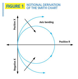
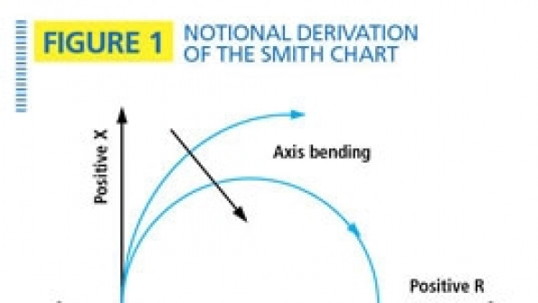
Impedance can be plotted in a rectangular-coordinate system, but the repeating cycle is very messy to represent. This behavior is much better represented on a polar-coordinate system. It helps to think of the problem in the following way: If we start with a rectangular-coordinate system like the one in Figure 1, and distort the reactance axis (y axis) into a number of circles with incrementally larger radii, we now represent constant resistance by a circle rather than a vertical line. Similarly, lines of constant reactance also become arcs, but with their ends at the chart edge.

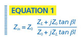
The Smith chart explained. The Smith chart is used to solve the transmission line impedance equation, where Z0 is the characteristic impedance of the transmission line (usually 50 ohms), ZL is the load impedance, b is the propagation constant of the line, and l is the distance on the line measured from the load. (See Equation 1.) Solving this equation is messy when done manually, but even when a computer is available, the Smith chart is the preferred solution because it aids understanding.

A simplified Smith chart is shown in Figure 2. Resistance is shown on the horizontal axis and lines of constant resistance are represented by circles that cross the horizontal axis and are aligned with the far right side of the chart. Zero resistance appears at the far left side of the horizontal axis and infinite resistance appears at the far right side. The system impedance of 50 ohms is at the center of the chart. (Most Smith Charts are normalized to a system impedance of 1 ohm, but the same principles apply.)

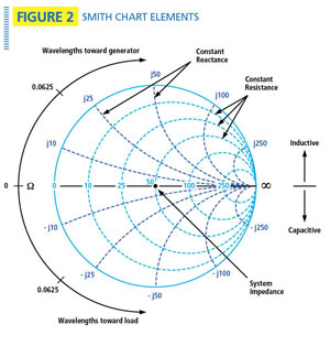
Lines of constant reactance are arcs with one end on the outside circle and the other end at infinity. Reactance above the horizontal axis is positive (inductive) while reactance below the horizontal axis is negative (capacitive). A line of constant standing wave ratio (SWR) is a circle centered at 50 ohms. A SWR of 1.0 is simply a point at the center of the chart, while an SWR of infinity is a circle coinciding with the outside edge of the chart. Moving clockwise is equivalent to moving toward the generator while moving counterclockwise is equivalent to moving toward the load. A complete circle equals 1/2 wavelength, or 180 electrical degrees.

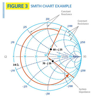
Let’s consider an example: One important use of the Smith chart is to calculate the impedance of the load when the only measurement available is at the end of a transmission line connected to the load. This problem commonly occurs when measuring the impedance of an antenna with a jumper cable permanently attached. Consider the specific case where an antenna comes with an attached coaxial jumper that is 3/8 wavelengths long. Using a network analyzer, we measure the impedance at the jumper’s connector to be Zin=60+j25 ohms. If we rotate this point 3/8 wavelengths counterclockwise (at the same SWR radius), we get a value of ZL = 70– j20 ohms, which is the impedance of the antenna. See Figure 3.

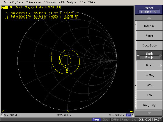
Other uses of the Smith Chart include the design of quarter-wave matching sections, antenna-tuning sections in general and observation of the frequency response of the load. Figure 4 below is an example of a frequency-swept measurement of a 900 MHz dipole antenna using an RF-network analyzer. Note that the antenna has best performance (lowest SWR) at roughly mid-band (915 MHz).

Jay Jacobsmeyer, KD0OFB, is president of Pericle Communications Co., a consulting engineering firm located in Colorado Springs, Colo. He holds bachelor’s and master’s degrees in electrical engineering from Virginia Tech and Cornell University, respectively, and has more than 30 years experience as a radio-frequency engineer.

Tags: Wireless Networks

Most Recent


  • AT&T wireless growth keyed by FirstNet—now provides 24,000 agencies with 4.4 million connections
    AT&T this week reported that FirstNet ended 2022 supporting more than 24,000 public-safety agencies with “about” 4.4 million connections, including 377,000 connections that were added during the last three months of 2022—a total that represents more than half of the carrier’s post-paid wireless growth for the quarter. AT&T officials released these figures in conjunction with […]
  • AT&T FirstNet unleashes robotic dogs for emergency services
    AT&T is releasing robotic hounds from Ghost Robotics as part of the service provider’s FirstNet emergency responder service. In a blog, AT&T VP Lance Spencer explained that the robotic dogs will be connected to AT&T’s network and deployed for public safety, defense, federal and state agencies, local police and fire departments, and commercial customers. “Network-connected robotic dogs can deliver a […]
  • How 5G is making cities safer, smarter, and more efficient
    It’s a scenario we’ve all experienced: an ambulance with a blaring siren racing against time to get a person in medical distress to a hospital through traffic. What we don’t see is 5G connectivity enabling paramedics to communicate with hospital staff via video conference and coordinate care in real-time before arriving at the emergency room. […]
  • MCPTT interworking for critical communications
    The goal of mission-critical communication systems is to minimize the response time of first responders in emergency situations across several agencies. A dedicated push-to-talk button offers an efficient mechanism that simplifies the speaker-to-listener process to a minimum. This feature is useful when coordinating large group activities and to enable the instant flow of tactical status […]

One comment

  1. Avatar kaishnadas Banerjee 4th November 2012 @ 12:52 pm
    Reply

    This is really good and easy
    This is really good and easy understandable book for myself

    Thanks and Regards
    K D Banerjee/India

Leave a comment Cancel reply

To leave a comment login with your Urgent Comms account:

Log in with your Urgent Comms account

Or alternatively provide your name, email address below:

Your email address will not be published. Required fields are marked *

Related Content

  • The battle over connected cars drags on
  • UK officials revamp ESN plans again, target Airwave-to-LTE transition for end of 2026
  • PSCR: Dereck Orr highlights features of June 21-24 virtual event
  • FirstNet buildout on pace for March 2023 completion, AT&T official says

Commentary


How 5G is making cities safer, smarter, and more efficient

26th January 2023

3GPP moves Release 18 freeze date to March 2024

18th January 2023

Do smart cities make safer cities?

  • 1
6th January 2023
view all

Events


UC Ezines


IWCE 2019 Wrap Up

13th May 2019
view all

Twitter


UrgentComm

AT&T wireless growth keyed by FirstNet—now provides 24,000 agencies with 4.4 million connections dlvr.it/ShY5qH

27th January 2023
UrgentComm

Report: Remote work causing offices to empty, but walkable cities still in high demand dlvr.it/ShXM7Z

27th January 2023
UrgentComm

AT&T FirstNet unleashes robotic dogs for emergency services dlvr.it/ShW7p8

27th January 2023
UrgentComm

Federal agencies infested by cyberattackers via legit remote-management systems dlvr.it/ShVhn3

26th January 2023
UrgentComm

How 5G is making cities safer, smarter, and more efficient dlvr.it/ShVS1h

26th January 2023
UrgentComm

MCPTT interworking for critical communications dlvr.it/ShTm3P

26th January 2023
UrgentComm

Self-driving cars present terrorism risk, FBI director says dlvr.it/ShTTHx

26th January 2023
UrgentComm

UK Home Office officially will cut ESN ties with Motorola Solutions in December dlvr.it/ShNjfN

24th January 2023

Newsletter

Sign up for UrgentComm’s newsletters to receive regular news and information updates about Communications and Technology.

Expert Commentary

Learn from experts about the latest technology in automation, machine-learning, big data and cybersecurity.

Business Media

Find the latest videos and media from the market leaders.

Media Kit and Advertising

Want to reach our digital and print audiences? Learn more here.

DISCOVER MORE FROM INFORMA TECH

  • American City & County
  • IWCE
  • Light Reading
  • IOT World Today
  • Mission Critical Technologies
  • TU-Auto

WORKING WITH US

  • About Us
  • Contact Us
  • Events
  • Careers

FOLLOW Urgent Comms ON SOCIAL

  • Privacy
  • CCPA: “Do Not Sell My Data”
  • Cookie Policy
  • Terms
Copyright © 2023 Informa PLC. Informa PLC is registered in England and Wales with company number 8860726 whose registered and Head office is 5 Howick Place, London, SW1P 1WG.